Lexus NX: Cruise Control Switch Circuit
DESCRIPTION
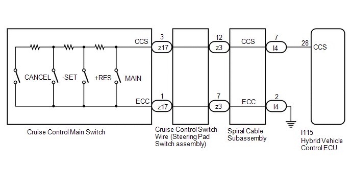
- The cruise control main switch outputs the cruise control power supply switch signal and each operation switch signal to the hybrid vehicle control ECU.
- The hybrid vehicle control ECU performs cruise control according to the signal from the cruise control main switch.
WIRING DIAGRAM
CAUTION / NOTICE / HINT
NOTICE:
- Before replacing the hybrid vehicle control ECU, refer to Service Bulletin.
-
The vehicle is equipped with a Supplemental Restraint System (SRS) which includes components such as airbags. Before servicing (including removal or installation of parts), be sure to read the precaution for Supplemental Restraint System.
Click here
.gif)
PROCEDURE
| 1. | READ VALUE USING TECHSTREAM |
(a) Connect the Techstream to the DLC3.
(b) Turn the power switch on (IG).
(c) Turn the Techstream on.
(d) Enter the following menus: Powertrain / Radar Cruise 1 / Data List.
(e) Read the Data List according to the display on the Techstream.
Powertrain > Radar Cruise1 > Data List| Tester Display | Measurement Item | Range | Normal Condition | Diagnostic Note |
|---|---|---|---|---|
| Cancel Switch | CANCEL switch status | ON or OFF | ON: CANCEL switch on OFF: CANCEL switch off | - |
| -SET Switch | -SET switch status | ON or OFF | ON: -SET switch on OFF: -SET switch off | - |
| +RES Switch | +RES switch status | ON or OFF | ON: +RES switch on OFF: +RES switch off | - |
| Cruise Ready Main-CPU | Cruise control system standby condition | ON or OFF | ON: Cruise control main switch (ON-OFF) on OFF: Cruise control main switch (ON-OFF) off | - |
| Cruise Ready Sub-CPU | Cruise control system standby condition | ON or OFF | ON: Cruise control main switch (ON-OFF) on OFF: Cruise control main switch (ON-OFF) off | - |
| Tester Display |
|---|
| Cancel Switch |
| -SET Switch |
| +RES Switch |
| Cruise Ready Main-CPU |
| Cruise Ready Sub-CPU |
OK:
The value of each Data List item changes according to the operation of the cruise control main switch.
| OK | .gif) | PROCEED TO NEXT SUSPECTED AREA SHOWN IN PROBLEM SYMPTOMS TABLE |
|
.gif)
| 2. | INSPECT CRUISE CONTROL MAIN SWITCH |
(a) Remove the cruise control main switch.
Click here
(b) Inspect the cruise control main switch.
Click here
| NG | | REPLACE CRUISE CONTROL MAIN SWITCH |
|
| 3. | CHECK CRUISE CONTROL SWITCH WIRE (STEERING PAD SWITCH ASSEMBLY) |
| (a) Remove the cruise control switch wire (steering pad switch assembly) Click here |
|
(b) Measure the resistance according to the value(s) in the table below.
Standard Resistance:
| Tester Connection | Condition | Specified Condition |
|---|---|---|
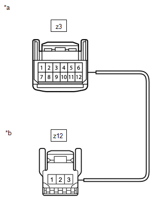
| z3-12 - z17-3 | Always | Below 1 Ω |
| z3-7 - z17-1 | Always | Below 1 Ω |
| z3-12 or z17-3 - Body ground | Always | 10 kΩ or higher |
| z3-7 or z17-1 - Body ground | Always | 10 kΩ or higher |
| NG | | REPLACE CRUISE CONTROL SWITCH WIRE (STEERING PAD SWITCH ASSEMBLY) |
|
| 4. | INSPECT SPIRAL CABLE SUB-ASSEMBLY |
(a) Remove the spiral cable sub-assembly.
Click here
(b) Inspect the spiral cable sub-assembly.
Click here
| NG | | REPLACE SPIRAL CABLE SUB-ASSEMBLY |
|
| 5. | CHECK HARNESS AND CONNECTOR (SPIRAL CABLE SUB-ASSEMBLY - HYBRID VEHICLE CONTROL ECU and BODY GROUND) |
(a) Disconnect the I4 spiral cable sub-assembly connector.
(b) Disconnect the A35 hybrid vehicle control ECU connector.
(c) Measure the resistance according to the value(s) in the table below.
Standard Resistance:
| Tester Connection | Condition | Specified Condition |
|---|---|---|
| I4-7 (CCS) - A35-55 (CCS) | Always | Below 1 Ω |
| I4-2 (ECC) - Body ground | Always | Below 1 Ω |
| I4-7 (CCS) or A35-55 (CCS) - Body ground | Always | 10 kΩ or higher |
| OK | | REPLACE HYBRID VEHICLE CONTROL ECU |
| NG | | REPAIR OR REPLACE HARNESS OR CONNECTOR |
READ NEXT:
 Distance Control Switch Circuit
DESCRIPTION The vehicle-to-vehicle distance control switch is used to set the distance for vehicle-to-vehicle distance control mode. The vehicle-to-vehicle distance control switch is installed in the
Cruise Main Indicator Light Circuit
DESCRIPTION When the dynamic radar cruise control system is turned on using the cruise control main switch, the cruise control indicator (vehicle-to-vehicle distance control mode) illuminates. The hyb
Cruise SET Indicator Light Circuit
DESCRIPTION The hybrid vehicle control ECU illuminates the cruise SET indicator by sending request signals to the combination meter assembly via CAN communication. The cruise SET indicator illuminates
SEE MORE:
Components
COMPONENTS ILLUSTRATION *1 DECK FLOOR BOX LH *2 NO. 3 DECK BOARD SUB-ASSEMBLY *3 REAR DECK FLOOR BOX *4 AUXILIARY BATTERY NEGATIVE TERMINAL N*m (kgf*cm, ft.*lbf): Specified torque - - ILLUSTRATION *1 COWL SIDE TRIM BOARD LH *2 DOOR SCUFF PLATE ASSEMBLY LH
Front Right Seat Heat Sensor Circuit (B14C0)
DESCRIPTION Output to the front seat cushion heater temperature sensor stops if one of the following occurs: 1) the temperature sensor is open or shorted; or 2) the temperature sensor is damaged and its output value does not change. DTC No. Detection Item DTC Detection Condition Trouble Are
