Lexus NX: Rear Door Courtesy Switch
Components
COMPONENTS
ILLUSTRATION
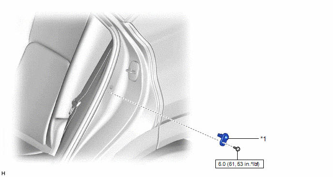
| *1 | REAR DOOR COURTESY LIGHT SWITCH ASSEMBLY | - | - |
.png) | N*m (kgf*cm, ft.*lbf): Specified torque | - | - |
Removal
REMOVAL
CAUTION / NOTICE / HINT
HINT:
- Use the same procedure for the RH and LH sides.
- The procedure listed below is for the LH side.
PROCEDURE
1. REMOVE REAR DOOR COURTESY LIGHT SWITCH ASSEMBLY
| (a) Using a T30 "TORX" socket wrench, remove the screw. |
|
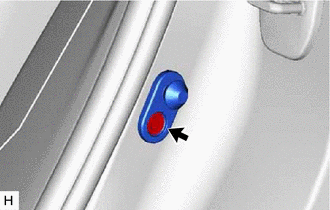
(b) Disconnect the connector and remove the rear door courtesy light switch assembly.
Inspection
INSPECTION
CAUTION / NOTICE / HINT
HINT:
- Use the same procedure for the RH and LH sides.
- The procedure listed below is for the LH side.
PROCEDURE
1. INSPECT REAR DOOR COURTESY LIGHT SWITCH ASSEMBLY
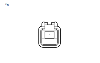
| (a) Measure the resistance according to the value(s) in the table below. Standard Resistance:
If the result is not as specified, replace the rear door courtesy light switch assembly. |
|
Installation
INSTALLATION
CAUTION / NOTICE / HINT
HINT:
- Use the same procedure for the RH and LH sides.
- The procedure listed below is for the LH side.
PROCEDURE
1. INSTALL REAR DOOR COURTESY LIGHT SWITCH ASSEMBLY
(a) Connect the connector.
(b) Using a T30 "TORX" socket wrench, install the rear door courtesy light switch assembly with the screw.
Torque:
6.0 N·m {61 kgf·cm, 53 in·lbf}
READ NEXT:
 Relay
Relay
On-vehicle InspectionON-VEHICLE INSPECTION PROCEDURE 1. INSPECT LIGHT CUT RELAY (a) Remove the upper instrument panel sub-assembly. Click here (b) Remove the light cut relay. (c
Room Light
ComponentsCOMPONENTS ILLUSTRATION *A for Normal Roof *B for Sliding Roof *C for Glass Roof - - *1 SPOT LIGHT ASSEMBLY (ROOM LIGHT) - - RemovalREMOVAL PROCEDURE 1. RE
Vanity Light
ComponentsCOMPONENTS ILLUSTRATION *1 VANITY LIGHT ASSEMBLY *2 VANITY LIGHT BULB *3 VANITY LIGHT HOLDER - - RemovalREMOVAL CAUTION / NOTICE / HINT HINT:
Use the same procedu
SEE MORE:
Diagnostic Trouble Code Chart
DIAGNOSTIC TROUBLE CODE CHART Smart Access System with Push-button Start (for Start Function) DTC No. Detection Item Link B2271 Ignition Hold Monitor Malfunction B2274 ACC Monitor Malfunction B2275 STSW Monitor Malfunction B2277 Detecting Vehicle Submers
System Description
SYSTEM DESCRIPTION GENERAL (a) This system uses ultrasonic sensors to detect any obstacles at the corners and the rear of the vehicle. The system then informs the driver of the distance between the sensors and an obstacle as well as their positions by indicating them on the multi-information display
