Lexus NX: Distance Control Switch Circuit
DESCRIPTION
The vehicle-to-vehicle distance control switch is used to set the distance for vehicle-to-vehicle distance control mode. The vehicle-to-vehicle distance control switch is installed in the steering pad switch assembly. The vehicle-to-vehicle distance set value can be changed by operating the vehicle-to-vehicle distance control switch while the dynamic radar cruise control system is controlling vehicle speed in vehicle-to-vehicle distance control mode.
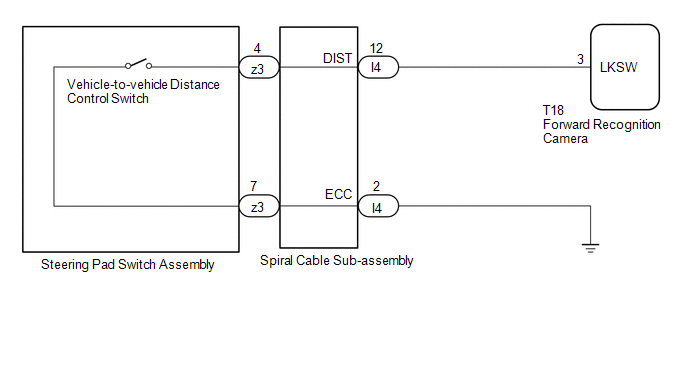
WIRING DIAGRAM
CAUTION / NOTICE / HINT
NOTICE:
-
The vehicle is equipped with a Supplemental Restraint System (SRS) which includes components such as airbags. Before servicing (including removal or installation of parts), be sure to read the precaution for Supplemental Restraint System.
Click here
.gif)
- When replacing the forward recognition camera, replace it with a new one. If a forward recognition camera which was installed to another vehicle is used, the information stored in the forward recognition camera will not match the information from the vehicle and a DTC may be stored.
-
When the forward recognition camera is replaced with a new one or the windshield glass is replaced or removed/installed, make sure to perform beam axis adjustment for the forward recognition camera and clear the vehicle control history for each system.
HINT:
Forward recognition camera adjustment can be performed by using either One Time Recognition or Sequential Recognition.
One Time Recognition: Click here
Sequential Recognition: Click here
PROCEDURE
| 1. | READ VALUE USING TECHSTREAM |
(a) Connect the Techstream to the DLC3.
(b) Turn the power switch on (IG).
(c) Turn the Techstream on.
(d) Enter the following menus: Powertrain / Radar Cruise2 / Data List.
(e) Read the Data List according to the display on the Techstream.
Powertrain > Radar Cruise2 > Data List| Tester Display | Measurement Item | Range | Normal Condition | Diagnostic Note |
|---|---|---|---|---|
| Vehicle-to-vehicle Distance Control Switch | Vehicle-to-vehicle distance control switch signal | ON or OFF | ON: Vehicle-to-vehicle distance control switch pushed OFF: Vehicle-to-vehicle distance control switch not pushed | - |
| Tester Display |
|---|
| Vehicle-to-vehicle Distance Control Switch |
OK:
The value of the Data List item changes according to the operation of the vehicle-to-vehicle distance control switch.
| OK | .gif) | PROCEED TO NEXT SUSPECTED AREA SHOWN IN PROBLEM SYMPTOMS TABLE |
|
.gif)
| 2. | INSPECT STEERING PAD SWITCH ASSEMBLY |
(a) Remove the steering pad switch assembly.
Click here
(b) Inspect the steering pad switch assembly.
Click here
| NG | | REPLACE STEERING PAD SWITCH ASSEMBLY |
|
| 3. | INSPECT SPIRAL CABLE SUB-ASSEMBLY |
(a) Remove the spiral cable sub-assembly.
Click here
(b) Inspect the spiral cable sub-assembly.
Click here
| NG | | REPLACE SPIRAL CABLE SUB-ASSEMBLY |
|
| 4. | CHECK HARNESS AND CONNECTOR (SPIRAL CABLE SUB-ASSEMBLY - FORWARD RECOGNITION CAMERA) |
(a) Disconnect the I4 spiral cable sub-assembly connector.
(b) Disconnect the T18 forward recognition camera connector.
(c) Measure the resistance according to the value(s) in the table below.
Standard Resistance:
| Tester Connection | Condition | Specified Condition |
|---|---|---|
| I4-12 (DIST) - T18-3 (LKSW) | Always | Below 1 Ω |
| I4-12 (DIST) or T18-3 (LKSW) - Body ground | Always | 10 kΩ or higher |
(d) Connect the T18 forward recognition camera connector.
(e) Connect the I4 spiral cable sub-assembly connector.
| NG | | REPAIR OR REPLACE HARNESS OR CONNECTOR |
|
| 5. | CHECK HARNESS AND CONNECTOR (SPIRAL CABLE SUB-ASSEMBLY - BODY GROUND) |
(a) Disconnect the I4 spiral cable sub-assembly connector.
(b) Measure the resistance according to the value(s) in the table below.
Standard Resistance:
| Tester Connection | Condition | Specified Condition |
|---|---|---|
| I4-2 (ECC) - Body ground | Always | Below 1 Ω |
(c) Connect the I4 spiral cable sub-assembly connector.
| OK | | USE SIMULATION METHOD TO CHECK |
| NG | | REPAIR OR REPLACE HARNESS OR CONNECTOR |
READ NEXT:
 Cruise Main Indicator Light Circuit
DESCRIPTION When the dynamic radar cruise control system is turned on using the cruise control main switch, the cruise control indicator (vehicle-to-vehicle distance control mode) illuminates. The hyb
Cruise SET Indicator Light Circuit
DESCRIPTION The hybrid vehicle control ECU illuminates the cruise SET indicator by sending request signals to the combination meter assembly via CAN communication. The cruise SET indicator illuminates
SEE MORE:
Components
COMPONENTS ILLUSTRATION *A w/ Steering Heater - - *1 CRUISE CONTROL MAIN SWITCH *2 SHIFT PADDLE SWITCH (TRANSMISSION SHIFT SWITCH ASSEMBLY) *3 STEERING PAD SWITCH ASSEMBLY *4 STEERING SHAKE DAMPER *5 STEERING WHEEL ASSEMBLY *6 STEERING WHEEL HEATER CONTROL ASS
Removal
REMOVAL PROCEDURE 1. REMOVE NO. 2 FORWARD RECOGNITION COVER Click here 2. REMOVE NO. 1 FORWARD RECOGNITION COVER Click here 3. REMOVE INNER REAR VIEW MIRROR ASSEMBLY (a) Disconnect the connector. *a Connector *b Screw (b) Detach the clamp. (c) Using a T20 "TORX
