Lexus NX: Customize Parameters
CUSTOMIZE PARAMETERS
CUSTOMIZE SMART ACCESS SYSTEM WITH PUSH-BUTTON START (for Entry Function)
HINT:
The following items can be customized.
NOTICE:
- When the customer requests a change in a function, first make sure that the function can be customized.
- Record the current settings before customizing.
(a) Customizing with the Techstream
(1) Connect the Techstream to the DLC3.
(2) Turn the power switch on (IG).
(3) Turn the Techstream on.
(4) Enter the following menus: Customize Setting / Wireless Door Lock, Smart Key / Access, Warning or PSD & PBD operation*.
- *: w/ Hands Free Power Back Door
(5) Select the setting by referring to the table below.
Wireless Door Lock| Tester Display | Description | Default | Setting | ECU |
|---|---|---|---|---|
| Wireless Control | Function that turns the wireless door lock control system on or off | ON | 0:OFF,1:ON | Main body ECU (Multiplex network body ECU) |
| Hazard Answer Back | When the doors are locked by the entry lock function, the hazard warning lights flash once. When the doors are unlocked by the entry lock function, the hazard warning lights flash twice. | ON | 0:OFF,1:ON | Main body ECU (Multiplex network body ECU) |
| Open Door Warning | The buzzer sounds when the lock sensor on the door outside handle assembly is touched to perform entry lock with a door open. | ON | 0:OFF,1:ON | Main body ECU (Multiplex network body ECU) |
| Auto Lock Time | Function that regulates the interval between unlocking and automatic relocking of doors. | 60 s | 00:30 s,01:60 s,10:120 s | Main body ECU (Multiplex network body ECU) |
| Wireless Buzzer Resp | Wireless buzzer response. | ON | 0:OFF,1:ON | Main body ECU (Multiplex network body ECU) |
| Wireless Buzzer Vol | Buzzer answer-back volume. | Level5 | 0000:Level7,0001:Level6,0010:Level5,0011:Level4,0100:Level3,0101:Level2,0110:Level1,0111:Level0 | Main body ECU (Multiplex network body ECU) |
| Tester Display | Description | Default | Setting | ECU |
|---|---|---|---|---|
| Key Low Battery Warning | Enables or disables the sounding of the buzzer when the transmitter battery is low and the power switch is turned off after being on (IG) for 20 minutes or more. | ON | 0:OFF,1:ON | Certification ECU (Smart key ECU assembly) |
| Tester Display | Description | Default | Setting | ECU |
|---|---|---|---|---|
| Park Wait Time | Function that sets the period of time (lock confirmation time) that the door is prevented from being unlocked by operating the front door outside handle assembly after an entry lock operation is performed. | 2.5s | 00:0.5s,01:1.5s,10:2.5s,11:5s | Certification ECU (Smart key ECU assembly) |
| Ignition Available Area | Function that sets the area that the key must be in before the power switch can be operated. | All | 00:Front,01:All | Certification ECU (Smart key ECU assembly) |
| Back Door Opening Operation | Function that sets the back door when the user is carrying the electrical key transmitter sub-assembly and presses the back door opener switch assembly (open switch). | Long | 00:Long,01:Twice,10:OFF | Certification ECU (Smart key ECU assembly) |
| Door Unlock Mode2 | Function that sets which doors are unlocked by the entry unlock function. | Driver | 0:All,1:Driver | Certification ECU (Smart key ECU assembly) |
| Touch Activation Over Threshold | The function that limits the consecutive entry lock operation to only 2 times can be changed between Active and Not Active. When in Not Active mode, there is no limit for the number of times that the consecutive entry lock operation can be performed. | Active | 0:Active,1:Not Active | Certification ECU (Smart key ECU assembly) |
| Engine Start Indicator | Function that turns the entry warning light on the combination meter assembly on or off. | ON | 0:OFF,1:ON | Certification ECU (Smart key ECU assembly) |
| Tester Display | Description | Default | Setting | ECU |
|---|---|---|---|---|
| Kick Sensor Function | Function that enables/disables the touchless power back door.* | ON | 0:OFF,1:ON | Multiplex network door ECU |
| Kick Sensor Operation with ACC ON | Status of the touchless power back door function with power switch on (ACC).* | Available | 0:Available,1:Not Available | Main body ECU (multiplex network body ECU) |
- *: w/ Hands Free Power Back Door
(b) Customizing with the multi-display
(1) Turn the power switch on (IG).
(2) Enter the following menus: SETUP / Vehicle / Vehicle customization / Door lock settings.
(3) Select the setting by referring to the table below.
| Display | Default | Content | Setting | Relevant ECU |
|---|---|---|---|---|
| Select Doors to Unlock | Driver's Door | Function that sets which doors are unlocked by the entry unlock function. | All Doors or Driver's Door | Certification ECU (Smart key ECU assembly) |
| Auto Relock Timer | 60 sec. | Function that turns the auto lock function on or off. | Off, 30 sec., 60 sec. or 120 sec. | Main body ECU (Multiplex network body ECU) |
| Lock/Unlock Feedback-Lights | On | When the doors are locked by the entry lock function, the hazard warning lights flash once. When the doors are unlocked by the entry lock function, the hazard warning lights flash twice. | On or Off | Main body ECU (Multiplex network body ECU) |
| Lock/Unlock Feedback-Tone | 5 | Buzzer answer-back volume. | Off, 1, 2, 3, 4, 5, 6 or 7 | Main body ECU (Multiplex network body ECU) |
| KICK SENSOR* | Function that can be used to set the hands free power back door. | On | On or Off | Multiplex network door ECU |
- *: w/ Hands Free Power Back Door
(c) Entry unlock mode switching function (manual operation)
(1) The following entry unlock modes can be selected when using the entry unlock mode switching function.
- All door unlock mode: When the sensor of a front door outside handle assembly is touched, an entry unlock operation is performed simultaneously for all doors.
- Driver door unlock mode: When the sensor of the driver side door outside handle assembly is touched, an entry unlock operation is performed for the driver door only. If any other door handle is touched, an entry unlock operation is performed simultaneously for all doors.
(2) When customizing through manual operation:
- Turn the power switch off.
- Check that the LED of the electrical key transmitter sub-assembly is not illuminated, and then press and hold the lock and unlock switches of the electrical key transmitter sub-assembly for 5 seconds or more while the electrical key transmitter sub-assembly is in the actuation area.
-
Check the current setting.
HINT:
- The mode changes from all door unlock mode to driver door unlock mode and then back to all door unlock mode.
-
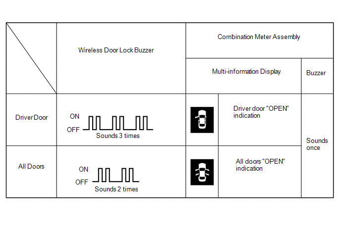
The answer-back (wireless buzzer, buzzer in the combination meter assembly) operation for each mode is indicated in the table below.
Currently Selected Mode
Answer-back (Wireless Buzzer)
Answer-back (Buzzer in Combination Meter Assembly)
All door unlock mode
Buzzer sounds twice (short beeps)
Buzzer sounds once
Driver door unlock mode
Buzzer sounds 3 times (short beeps)
Buzzer sounds once
- Release the lock and unlock switches of the electrical key transmitter sub-assembly.
-
Check that the LED of the electrical key transmitter sub-assembly is not illuminated, and then press and hold the lock and unlock switches of the electrical key transmitter sub-assembly for 5 seconds or more to change the mode.
HINT:
Repeat the procedure as necessary to select the desired mode.
-
Unlock the doors with the wireless operation, and then open any door.
(d) Entry cancel function (manual operation)
HINT:
While the smart access system with push-button start is canceled, it is possible to lock and unlock the doors with the wireless operation, and the start system can be operated by holding the electrical key transmitter sub-assembly near the power switch.
(1) The following functions are disabled when the smart access system with push-button start is canceled.
- Entry unlock/lock functions
- Push-button start function
- Key lock-in prevention function
- Entry warning functions
(2) When canceling the smart access system with push-button start through manual operation:
-
Make sure the following conditions are met:
- The power switch is off.
- The driver door is closed.
- The driver door is unlocked.
(3) Press the unlock switch of the electrical key transmitter sub-assembly.
(4) Open the driver door within 5 seconds of completing the step above (driver door: closed → opened).
(5) With the driver door open, press the unlock switch of the electrical key transmitter sub-assembly 2 times within 5 seconds of completing the step above.
NOTICE:
If the driver door is closed before or while pressing the unlock switch, the entry cancel setting mode will end.
(6) Perform the following procedure within 30 seconds of completing the step above.
- Close and open the driver door twice (driver door: open → closed → opened → closed → opened).
-
With the driver door open, press the unlock switch of the electrical key transmitter sub-assembly 2 times.
NOTICE:
If the driver door is closed before or while pressing the unlock switch, the entry cancel setting mode will end.
- Close and open the driver door (driver door: open → closed → opened).
(7) Close the driver door within 5 seconds (driver door: open → closed).
(8) Check that the wireless buzzer sounds twice (short beeps) to confirm that the smart access system with push-button start has been canceled.
(9) Perform the following procedure to restore the smart access system with push-button start to the active state from the canceled state.
- Perform the procedure to cancel the smart access system with push-button start again.
-
Check that the wireless buzzer sounds once (short beep) to confirm that the smart access system with push-button start has been restored to the active state.
HINT:
- The system changes between the canceled state and the active state each time the procedure to cancel the system through manual operation is performed.
- The buzzer sounds twice when the system changes from the active state to the canceled state, and sounds once when the system changes from the canceled state to the active state.
READ NEXT:
 Problem Symptoms Table
PROBLEM SYMPTOMS TABLE HINT:
If a problem occurs in certain locations or at certain times of day, check for the possibility of wave interference.
When the electrical key transmitter sub-assembly
Terminals Of Ecu
TERMINALS OF ECU CHECK CERTIFICATION ECU (SMART KEY ECU ASSEMBLY) (a) Disconnect the I53 certification ECU (smart key ECU assembly) connector. (b) Measure the voltage and resistance according to the
Diagnosis System
DIAGNOSIS SYSTEM DESCRIPTION (a) Smart access system with push-button start (for Entry Function) data and Diagnostic Trouble Codes (DTCs) can be read through the vehicle Data Link Connector 3 (DLC3).
SEE MORE:
Diagnostic Trouble Code Chart
DIAGNOSTIC TROUBLE CODE CHART Smart Access System with Push-button Start (for Start Function) DTC No. Detection Item Link B2271 Ignition Hold Monitor Malfunction B2274 ACC Monitor Malfunction B2275 STSW Monitor Malfunction B2277 Detecting Vehicle Submers
ASC ECU Communication Stop Mode
DESCRIPTION Detection Item Symptom Trouble Area ASC ECU Communication Stop Mode Any of the following conditions are met:
Communication stop for "ASC" is indicated on the "Communication Bus Check" screen of the Techstream.
Click here
Communication system DTCs (DTCs that start wi
