Lexus NX: Headlight Cleaner Control Relay (for Single Beam Headlight)
Components
COMPONENTS
ILLUSTRATION
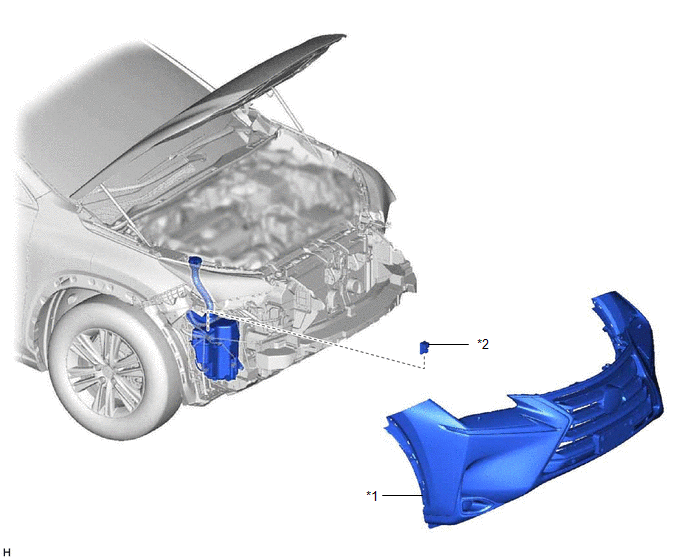
| *1 | FRONT BUMPER COVER | *2 | HEADLIGHT CLEANER CONTROL RELAY |
On-vehicle Inspection
ON-VEHICLE INSPECTION
PROCEDURE
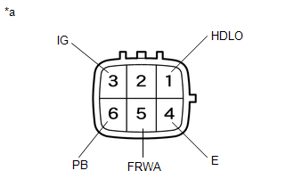
1. INSPECT HEADLIGHT CLEANER CONTROL RELAY
| (a) Measure the resistance according to the value(s) in the table below. Standard Resistance:
If the result is not as specified, replace the headlight cleaner control relay. |
|
Removal
REMOVAL
PROCEDURE
1. REMOVE FRONT BUMPER ASSEMBLY
(a) Remove the front bumper assembly.
(1) for Sport Package:
Click here .gif)
(2) except Sport Package:
Click here
2. REMOVE HEADLIGHT CLEANER CONTROL RELAY
| (a) Disconnect the connector. |
|
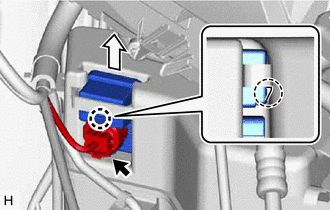
(b) Detach the claw and remove the headlight cleaner control relay.
Installation
INSTALLATION
PROCEDURE
1. INSTALL HEADLIGHT CLEANER CONTROL RELAY
| (a) Attach the claw to install the headlight cleaner control relay. |
|
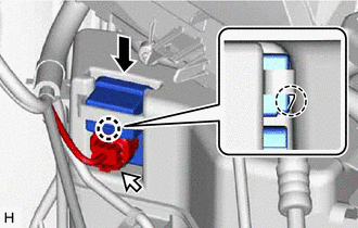
(b) Connect the connector.
2. INSTALL FRONT BUMPER ASSEMBLY
(a) Install the front bumper assembly.
(1) for Sport Package:
Click here .gif)
(2) except Sport Package:
Click here
READ NEXT:
 Headlight Cleaner Control Relay(for Triple Beam Headlight)
On-vehicle InspectionON-VEHICLE INSPECTION PROCEDURE 1. INSPECT HEADLIGHT CLEANER CONTROL RELAY (a) Remove the headlight cleaner control relay. (b) Measure the resistance according to the value(s)
Headlight Cleaner Motor
ComponentsCOMPONENTS ILLUSTRATION *1 FRONT BUMPER ASSEMBLY *2 HEADLIGHT CLEANER MOTOR AND PUMP ASSEMBLY RemovalREMOVAL PROCEDURE 1. REMOVE FRONT BUMPER ASSEMBLY Click here 2. REMOVE
SEE MORE:
Installation
INSTALLATION PROCEDURE 1. INSTALL ACCELERATION SENSOR (a) for RH side: (1) Install the acceleration sensor with the 2 nuts. Torque: 8.5 N·m {87 kgf·cm, 75 in·lbf} NOTICE:
Avoid any impact to the acceleration sensor.
Do not drop the acceleration sensor. If it is dropped, replace it with a ne
PIG Power Supply Voltage (C1552,C1554)
DESCRIPTION When a problem occurs in the power steering system, the power source relay circuit is shut off to stop the power assist. DTC No. Detection Item DTC Detection Condition Trouble Area Warning Indicate Return-to-normal Condition C1552 PIG Power Supply Voltage PIG power s
