Lexus NX: Daytime Running Light Relay Circuit
DESCRIPTION
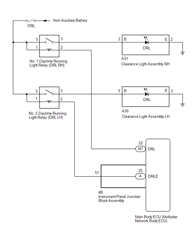
The illumination of the daytime running light (clearance light assembly) or clearance light is controlled by the headlight light control ECU sub-assembly.
WIRING DIAGRAM
CAUTION / NOTICE / HINT
NOTICE:
Inspect the fuses for circuits related to this system before performing the following inspection procedure.
PROCEDURE
| 1. | PERFORM ACTIVE TEST USING TECHSTREAM (DAYTIME RUNNING LIGHT) |
(a) Using the Techstream, perform the Active Test.
Click here .gif)
| Tester Display | Measurement Item | Control Range | Diagnostic Note |
|---|---|---|---|
| Daytime Running Light | Illuminates daytime running lights | ON or OFF | - |
| Tester Display |
|---|
| Daytime Running Light |
| Result | Proceed to |
|---|---|
| The Active Test is performed normally | A |
| The Active Test is not performed normally for the right side light only | B |
| The Active Test is not performed normally for the left side light only | C |
| A | .gif) | PROCEED TO NEXT SUSPECTED AREA SHOWN IN PROBLEM SYMPTOMS TABLE |
| C | | GO TO STEP 5 |
|
.gif)
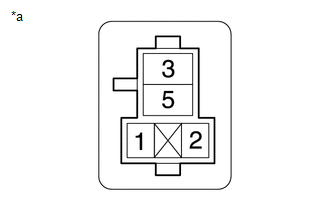
| 2. | INSPECT NO. 1 DAYTIME RUNNING LIGHT RELAY (DRL RH) |
(a) Remove the No. 1 daytime running light relay from the No. 2 engine room relay block.
(b) Inspect the No. 1 daytime running light relay.
Click here
| NG | | REPLACE NO. 1 DAYTIME RUNNING LIGHT RELAY (DRL RH) |
|
| 3. | CHECK HARNESS AND CONNECTOR (NO. 1 DAYTIME RUNNING LIGHT RELAY [DRL RH] - BATTERY) |
(a) Remove the No. 1 daytime running light relay from the No. 2 engine room relay block.
| (b) Measure the voltage according to the value(s) in the table below. Standard Voltage:
|
|
| NG | | REPAIR OR REPLACE HARNESS OR CONNECTOR |
|
| 4. | CHECK HARNESS AND CONNECTOR (NO. 1 DAYTIME RUNNING LIGHT RELAY [DRL RH] - MAIN BODY ECU [MULTIPLEX NETWORK BODY ECU]) |
(a) Remove the No. 1 daytime running light relay from the No. 2 engine room relay block.
(b) Remove the instrument panel junction block assembly.
(c) Disconnect the I47 instrument panel junction block assembly connector.
(d) Measure the resistance according to the value(s) in the table below.
Standard Resistance:
| Tester Connection | Condition | Specified Condition |
|---|---|---|
| Relay terminal 2 - I47-22 (DRL) | Always | Below 1 Ω |
| Relay terminal 2 or I47-22 (DRL) - Body ground | Always | 10 kΩ or higher |
| OK | | REPLACE MAIN BODY ECU (MULTIPLEX NETWORK BODY ECU) |
| NG | | REPAIR OR REPLACE HARNESS OR CONNECTOR |
| 5. | INSPECT NO. 2 DAYTIME RUNNING LIGHT RELAY (DRL LH) |
(a) Remove the No. 2 daytime running light relay from the No. 2 engine room relay block.
(b) Inspect the No. 1 daytime running light relay.
Click here
| NG | | REPLACE NO. 2 DAYTIME RUNNING LIGHT RELAY (DRL LH) |
|
| 6. | CHECK HARNESS AND CONNECTOR (NO. 2 DAYTIME RUNNING LIGHT RELAY [DRL LH] - BATTERY) |
(a) Remove the No. 2 daytime running light relay from the No. 2 engine room relay block.
| (b) Measure the voltage according to the value(s) in the table below. Standard Voltage:
|
|
| NG | | REPAIR OR REPLACE HARNESS OR CONNECTOR |
|
| 7. | CHECK HARNESS AND CONNECTOR (NO. 2 DAYTIME RUNNING LIGHT RELAY [DRL LH] - MAIN BODY ECU [MULTIPLEX NETWORK BODY ECU]) |
(a) Remove the No. 2 daytime running light relay from the No. 2 engine room relay block.
(b) Remove the instrument panel junction block assembly.
(c) Disconnect the 4B instrument panel junction block assembly connector.
(d) Measure the resistance according to the value(s) in the table below.
Standard Resistance:
| Tester Connection | Condition | Specified Condition |
|---|---|---|
| Relay terminal 2 - 4B-51 | Always | Below 1 Ω |
| Relay terminal 2 or 4B-51 - Body ground | Always | 10 kΩ or higher |
| OK | | REPLACE MAIN BODY ECU (MULTIPLEX NETWORK BODY ECU) |
|
| 8. | INSPECT INSTRUMENT PANEL JUNCTION BLOCK ASSEMBLY |
(a) Remove the driver side junction block assembly.
Click here
| (b) Remove the main body ECU from the driver side junction block assembly. Click here |
|
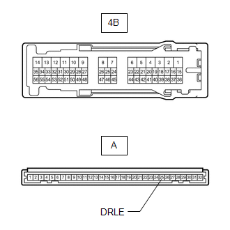
(c) Measure the resistance according to the value(s) in the table below.
Standard Resistance:
| Tester Connection | Condition | Specified Condition |
|---|---|---|
| A-25 (DRLE) - 4B-51 | Always | Below 1 Ω |
| OK | | REPLACE INSTRUMENT PANEL JUNCTION BLOCK ASSEMBLY |
| NG | | REPAIR OR REPLACE HARNESS OR CONNECTOR |
READ NEXT:
 Front Fog Light Circuit
DESCRIPTION Illumination of the front fog lights is controlled by the main body ECU (multiplex network body ECU). WIRING DIAGRAM CAUTION / NOTICE / HINT NOTICE:
Inspect the fuses for circuits rela
Hazard Warning Switch Circuit
DESCRIPTION When the combination meter receives a hazard warning signal switch signal, the flasher IC turns on and hazard control is performed. WIRING DIAGRAM CAUTION / NOTICE / HINT NOTICE: When rep
Taillight Relay Circuit
DESCRIPTION Illumination of the taillights and license plate light is controlled by the main body ECU (multiplex network body ECU). WIRING DIAGRAM CAUTION / NOTICE / HINT NOTICE:
Inspect the fuse
SEE MORE:
Installation
INSTALLATION PROCEDURE 1. INSTALL NO. 2 ECM BRACKET (a) Install the No. 2 ECM bracket to the ECM with the 2 screws. Torque: 3.0 N·m {31 kgf·cm, 27 in·lbf} 2. INSTALL NO. 1 ECM BRACKET (a) Install the No. 1 ECM bracket to the ECM with the 2 screws. Torque: 3.0 N·m {31 kgf·cm, 27 in·lbf} 3. IN
Diagnosis System
DIAGNOSIS SYSTEM FUNCTION OF WARNING INDICATOR AND MESSAGE (a) If the pre-collision system is not functioning properly, the driver is warned by the PCS warning light and a warning message displayed on the multi-information display. Master Warning Indicator Warning Message Detail DTC/RoB P
