Lexus NX: Taillight Relay Circuit
DESCRIPTION
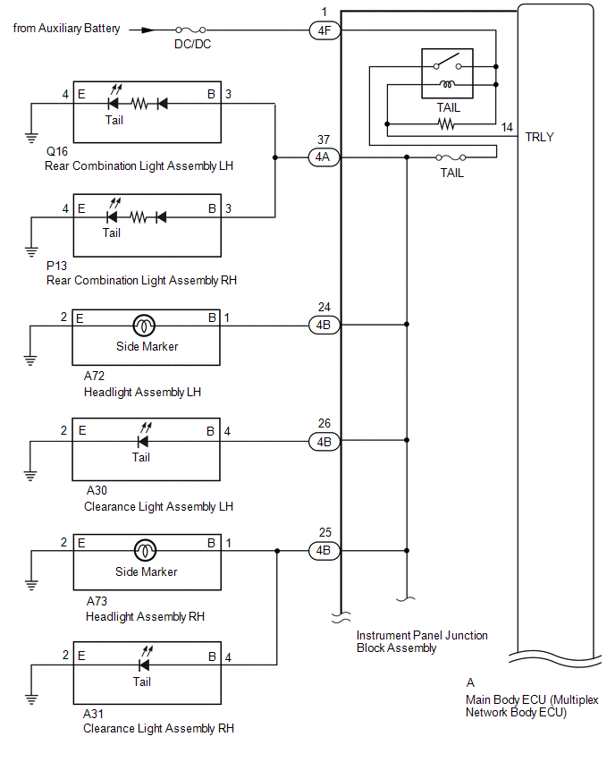
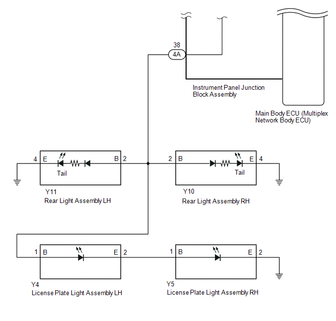
Illumination of the taillights and license plate light is controlled by the main body ECU (multiplex network body ECU).
WIRING DIAGRAM
CAUTION / NOTICE / HINT
NOTICE:
- Inspect the fuses for circuits related to this system before performing the following procedure.
- Recognition code registration is necessary when replacing the main body ECU (multiplex network body ECU).
- If the main body ECU (multiplex network body ECU) is replaced, refer to Registration.
PROCEDURE
| 1. | PERFORM ACTIVE TEST USING TECHSTREAM (TAILLIGHT RELAY) |
(a) Using the Techstream, perform the Active Test.
Click here .gif)
| Tester Display | Measurement Item | Control Range | Diagnostic Note |
|---|---|---|---|
| Taillight Relay | Taillight relay | ON or OFF | - |
| Tester Display |
|---|
| Taillight Relay |
| Result | Proceed to |
|---|---|
| Taillights, license lights, clearance light and side marker lights come on | A |
| Taillights, license lights, clearance light and side marker lights do not come on | B |
| A | .gif) | PROCEED TO NEXT SUSPECTED AREA SHOWN IN PROBLEM SYMPTOMS TABLE |
|
.gif)
| 2. | CHECK HARNESS AND CONNECTOR (INSTRUMENT PANEL JUNCTION BLOCK ASSEMBLY - BATTERY) |
(a) Disconnect the instrument panel junction block assembly connector.
| (b) Measure the voltage according to the value(s) in the table below. Standard Voltage:
|
|
| NG | | REPAIR OR REPLACE HARNESS OR CONNECTOR |
|
| 3. | INSPECT INSTRUMENT PANEL JUNCTION BLOCK ASSEMBLY |
(a) Remove the instrument panel junction block assembly.
Click here
(b) Remove the instrument panel junction block assembly.
Click here
(c) Measure the voltage according to the value(s) in the table below.
Standard Voltage:
| Tester Connection | Condition | Specified Condition |
|---|---|---|
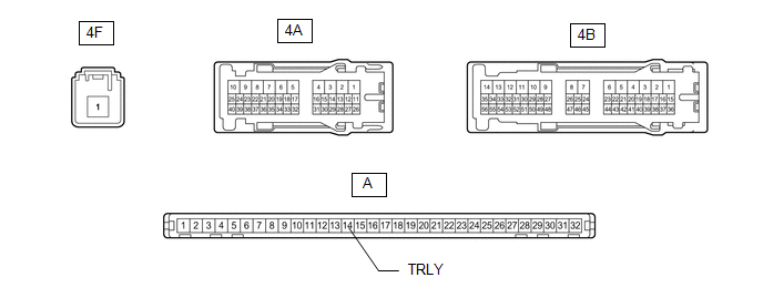
| 4A-37 - Battery negative (-) terminal | Battery voltage applied between terminals 4F-1 and A-14 (TRLY) | 11 to 14 V |
| Battery voltage not applied between terminals 4F-1 and A-14 (TRLY) | Below 1 V | |
| 4A-38 - Battery negative (-) terminal | Battery voltage applied between terminals 4F-1 and A-14 (TRLY) | 11 to 14 V |
| Battery voltage not applied between terminals 4F-1 and A-14 (TRLY) | Below 1 V | |
| 4B-24 - Battery negative (-) terminal | Battery voltage applied between terminals 4F-1 and A-14 (TRLY) | 11 to 14 V |
| Battery voltage not applied between terminals 4F-1 and A-14 (TRLY) | Below 1 V | |
| 4B-25 - Battery negative (-) terminal | Battery voltage applied between terminals 4F-1 and A-14 (TRLY) | 11 to 14 V |
| Battery voltage not applied between terminals 4F-1 and A-14 (TRLY) | Below 1 V | |
| 4B-26 - Battery negative (-) terminal | Battery voltage applied between terminals 4F-1 and A-14 (TRLY) | 11 to 14 V |
| Battery voltage not applied between terminals 4F-1 and A-14 (TRLY) | Below 1 V |
| OK | | REPLACE MAIN BODY ECU (MULTIPLEX NETWORK BODY ECU) |
| NG | | REPLACE INSTRUMENT PANEL JUNCTION BLOCK ASSEMBLY |
READ NEXT:
 Low Beam Headlight Circuit
DESCRIPTION The main body ECU (multiplex network body ECU) controls the low beam headlights. WIRING DIAGRAM CAUTION / NOTICE / HINT NOTICE:
Inspect the fuses for circuits related to this system be
High Beam Headlight Circuit
DESCRIPTION The main body ECU (multiplex network body ECU) controls the high beam headlights. WIRING DIAGRAM CAUTION / NOTICE / HINT NOTICE:
Inspect the fuses for circuits related to this system b
SEE MORE:
Blind Spot Monitor Main Switch
InspectionINSPECTION PROCEDURE 1. INSPECT COMBINATION SWITCH ASSEMBLY (BLIND SPOT MONITOR MAIN SWITCH) (a) Remove the combination switch assembly. Click here (b) Measure the resistance according to the value(s) in the table below. Standard Resistance: Tester Connection Switch Condition
Inverter Coolant Pump Speed Signal (P314A-828)
DESCRIPTION Refer to the description for DTC P0C73-776. Click here The inverter water pump assembly sends the inverter water pump speed (measured value) signal to the hybrid vehicle control ECU. If the inverter water pump speed (measured value) signal is not sent to the hybrid vehicle control ECU
