- +B
- Inverter Coolant Water Temperature
- Short Wave Highest Val
Lexus NX: DC / DC Converter Status Circuit (P0A08-264)
Lexus NX Service Manual / Engine & Hybrid System / 2ar-fxe (hybrid / Battery Control) / Hybrid Control System / DC / DC Converter Status Circuit (P0A08-264)
DESCRIPTION
The DC/DC converter converts the DC 244.8 V of the HV battery into DC 12 V in order to supply power to areas such as the vehicle's lighting, audio, and ECU systems. In addition, it charges the auxiliary battery.
A transistor bridge circuit initially converts DC 244.8 V into alternating current, and a transformer lowers the voltage. Then, it is rectified and smoothed (into direct current) and converted into DC 12 V. The DC/DC converter controls the output voltage in order to keep a constant voltage at the terminals of the auxiliary battery.
The hybrid vehicle control ECU sends a signal to the DC/DC converter to prohibit its control and receives signals indicating a normal or abnormal condition of the 12 V charging system via the NODD signal line.
If the DC/DC converter malfunctions, the vehicle will become inoperative. Therefore, the hybrid vehicle control ECU monitors the operation of the DC/DC converter and detects malfunctions.
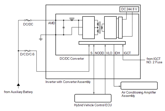
This DTC is stored when the DC/DC converter circuit has a malfunction or its operation is prohibited by a fail-safe function, or the auxiliary battery voltage drops to 11 V or less with the power switch on (READY). A signal indicating an auxiliary battery malfunction is sent from the DC/DC converter to the hybrid vehicle control ECU via the NODD signal line.
| DTC No. | Detection Item | DTC Detection Condition | Trouble Area | MIL | Warning Indicate |
|---|---|---|---|---|---|
| P0A08-264 | DC / DC Converter Status Circuit | The DC/DC converter is malfunctioning (charging has stopped) and the auxiliary battery voltage drops to 11 V or less. (1 trip detection logic) The DC/DC converter is malfunctioning for 120 seconds and the inverter coolant water temperature is 70°C or lower. (1 trip detection logic) |
| Does not come on | Master Warning Light: Comes on |
| DTC No. | ECU Data List |
|---|---|
| P0A08-264 | |
HINT:
- When the NODD signal line is open, DC/DC converter control is prohibited and the auxiliary battery voltage will be approximately 12 V (or less).
- Regarding NODD signal circuit, when the transistor of the hybrid vehicle control ECU turns on, a signal is sent to the inverter to prohibit DC/DC converter control. Sends a malfunction signal to the hybrid vehicle control ECU when the inverter side transistor is on.
- If the inverter is overheating, control may be suspended for self-protection of the DC/DC converter and this DTC may be stored.
WIRING DIAGRAM
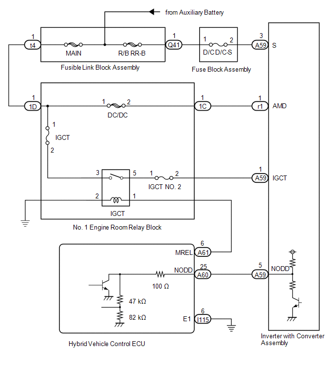
Refer to the wiring diagram for DTC P0AA6-526.
Click here .gif)
CAUTION / NOTICE / HINT
CAUTION:
- Before inspecting the high-voltage system or disconnecting the low voltage connector of the inverter with converter assembly, take safety precautions such as wearing insulated gloves and removing the service plug grip to prevent electrical shocks. After removing the service plug grip, put it in your pocket to prevent other technicians from accidentally reconnecting it while you are working on the high-voltage system.
-
After removing the service plug grip, wait for at least 10 minutes before touching any of the high-voltage connectors or terminals. After waiting for 10 minutes, check the voltage at the terminals in the inspection point in the inverter with converter assembly. The voltage should be 0 V before beginning work.
Click here
HINT:
Waiting for at least 10 minutes is required to discharge the high-voltage capacitor inside the inverter with converter assembly.
NOTICE:
After turning the power switch off, waiting time may be required before disconnecting the cable from the negative (-) auxiliary battery terminal. Therefore, make sure to read the disconnecting the cable from the negative (-) auxiliary battery terminal notices before proceeding with work.
Click here
HINT:
-
After repair, clear the DTCs, turn the power switch off and wait for 30 seconds or more and perform the following procedure to confirm that the auxiliary battery low voltage indicated by this DTC has been repaired.
-
Wait for 2 minutes with the shift lever in P, the power switch on (READY) and the following conditions met, then confirm that Data List item "+B" is between 13.0 and 15.0 V.
(If charging is not performed and the electrical load increases, +B voltage may not be steady and gradually drops.)
- Headlight switch is in the HI position.
- A/C blower fan switch is in the HI position.
- Window defogger switch is turned on.
-
Wait for 2 minutes with the shift lever in P, the power switch on (READY) and the following conditions met, then confirm that Data List item "+B" is between 13.0 and 15.0 V.
-
By performing the following procedure, the DC/DC converter function can be checked.
-
Connect the AC/DC 400 A probe to the positive auxiliary battery cable.
- Turn the power switch on (READY) and leave the vehicle as it is until the electric current flowing to the auxiliary battery becomes 10 A or less.
- Turn the power switch on (READY) and the headlight switch and A/C blower fan switch in the HI position, and the window defogger turned on.
- Confirm that the current drawn from the auxiliary battery is 0 A or lower and the auxiliary battery voltage is between 13.0 and 15.0 V.
-
Connect the AC/DC 400 A probe to the positive auxiliary battery cable.
- This DTC may be also stored when a part other than the DC/DC converter is malfunctioning or depending on user operation.
| Related Part, Inspection | Note | Inspection Step |
|---|---|---|
| R/B RR-B fuse is blown (fusible link block assembly) | - | 2 |
| Fuse is blown (D/C D/C-S) | - | 3 |
| A signal line connector of the hybrid vehicle control ECU or inverter is not connected securely | - | 4, 5 |
| A fusible link is blown (DC/DC) | 6 | |
| High-voltage insulation fault of the following (ground to body). - Between the motor and inverter - Between the generator and inverter - Between the rear motor and inverter | DTC P0A08-264 may be stored if the ground potential fluctuates due to a high-voltage insulation malfunction. | 7, 21 to 23, 28 to 30 |
| Check low-voltage line from the inverter to the hybrid vehicle control ECU | Inspect the continuity and connection condition of the AMD and S lines. | 8 to 11 |
| NODD signal line |
| 12, 24 |
| The DC/DC converter is malfunctioning | Inspect the DC/DC converter function. | 13 |
| DC/DC converter control is suspended due to overheating (inverter water pump with motor assembly is malfunctioning, the coolant is not sufficient, a hose is clogged, etc.) | When the inverter is overheating, the DC/DC converter has a self-protection function that may suspend the DC/DC converter control and output a DTC. The suspended DC/DC converter control will return to normal by clearing the DTCs and turning the power switch off. | 14 to 17, 25 |
| Check areas that caused the blown R/B RR-B fuse (fusible link block assembly) | - | 18, 26 |
| Check areas that caused the blown fuse (D/C D/C-S) | - | 19, 20, 27 |
- If this vehicle is used to jump start another vehicle with a discharged battery, a fuse may blow due to overcurrent or the DC/DC converter self-protection may be activated. Also, if this vehicle is jump started by a vehicle with a 24 V battery, the same malfunction may occur and this DTC may be stored. (The suspended DC/DC converter control will return to normal by clearing the DTCs and turning the power switch off.)
- Confirm that high electrical load equipment such as a high-capacitance audio device or electric kettle is used on the vehicle. (A fuse of the auxiliary battery may be blown due to overcurrent.)
- If the DC/DC converter is malfunctioning, the auxiliary battery cannot be charged. Therefore, once the power switch is turned off, it may be impossible to turn it on (READY) again if the auxiliary battery is completely discharged. In this case, charge the auxiliary battery. Be careful as charging is not performed during the inspection.
- If the power switch turns off immediately after it is turned on (READY), the auxiliary battery voltage may be low. Charge the auxiliary battery.
PROCEDURE
| 1. | CHECK DTC OUTPUT (HYBRID CONTROL) |
(a) Connect the Techstream to the DLC3.
(b) Turn the power switch on (IG).
(c) Enter the following menus: Powertrain / Hybrid Control / Trouble Codes.
(d) Check for DTCs.
Powertrain > Hybrid Control > Trouble Codes| Result | Proceed to |
|---|---|
| P0A08-264 only is output, or DTCs except the ones in the table below are also output. | A |
| Any of the following DTCs including pending DTCs are also output. | B |
| Relevant DTC | |
|---|---|
| P0A1B-547 | Drive Motor "A" Control Module |
| P0A40-549 | Drive Motor "A" Position Sensor Circuit Range / Performance |
| P0A78-548 | Drive Motor "A" Inverter Performance |
| P0A93-346 | Inverter Cooling System Performance |
| P0AA6-526, 613, 655 | Hybrid Battery Voltage System Isolation Fault |
| P0ADB-227 | Hybrid Battery Positive Contactor Control Circuit Low |
| P0ADF-229 | Hybrid Battery Negative Contactor Control Circuit Low |
| P0AE6-225 | Hybrid Battery Precharge Contactor Control Circuit Low |
| P0C73-776 | Motor Electronics Coolant Pump "A" Control Performance |
| P3004-131, 803 | High Voltage Power Resource |
| P314A-828 | Inverter Coolant Pump Speed Signal |
(e) Turn the power switch off.
| B | .gif) | GO TO DTC CHART (HYBRID CONTROL SYSTEM) |
|
.gif)
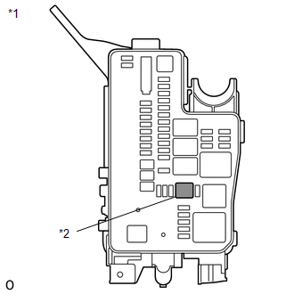
| 2. | CHECK FUSIBLE LINK BLOCK ASSEMBLY |
(a) Remove the fusible link block assembly.
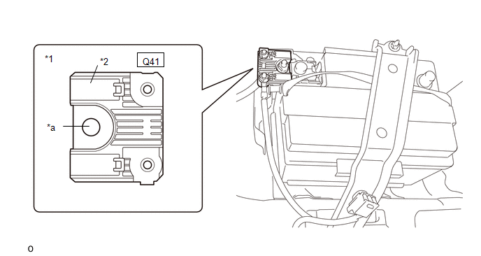
| *1 | Fusible Link Block Assembly | *2 | R/B RR-B fuse |
| *a | Auxiliary Battery Positive (+) Connection | - | - |
(b) Measure the resistance according to the value(s) in the table below.
Standard Resistance:
| Tester Connection | Condition | Specified Condition |
|---|---|---|
| Q41-1 - Auxiliary battery positive (+) connection | Always | Below 1 Ω |
(c) Install the fusible link block assembly.
| NG | | GO TO STEP 18 |
|
| 3. | CHECK FUSE (D/C D/C-S) |
| (a) Remove the D/C D/C-S fuse from the fuse block assembly. |
|
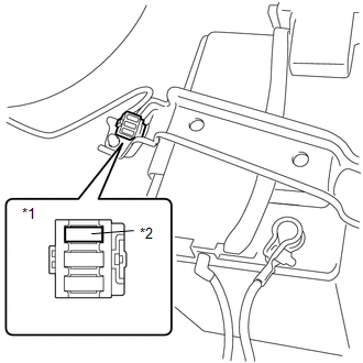
(b) Measure the resistance according to the value(s) in the table below.
Standard Resistance:
| Tester Connection | Condition | Specified Condition |
|---|---|---|
| D/C D/C-S fuse terminals | Always | Below 1 Ω |
(c) Install the D/C D/C-S fuse.
| NG | | GO TO STEP 19 |
|
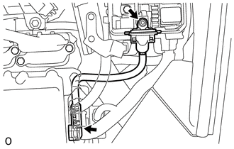
| 4. | CHECK CONNECTOR CONNECTION CONDITION (HYBRID VEHICLE CONTROL ECU CONNECTOR) |
Click here
| NG | | CONNECT SECURELY |
|
| 5. | CHECK CONNECTOR CONNECTION CONDITION (INVERTER WITH CONVERTER ASSEMBLY CONNECTOR) |
Click here
| Result | Proceed to |
|---|---|
| OK | A |
| NG (The connector is not connected securely.) | B |
| NG (The terminals are not making secure contact or are deformed, or water or foreign matter exists in the connector.) | C |
| B | | CONNECT SECURELY |
| C | | REPAIR OR REPLACE HARNESS OR CONNECTOR |
|
| 6. | CHECK FUSE (DC/DC) |
| (a) Check the DC/DC fuse in the No. 1 engine room relay block for improper installation. OK: The fuse is installed securely. |
|
(b) Remove the DC/DC fuse from the No. 1 engine room relay block.
(c) Measure the resistance according to the value(s) in the table below.
Standard Resistance:
| Tester Connection | Condition | Specified Condition |
|---|---|---|
| DC/DC fuse terminals | Always | Below 1 Ω |
(d) Install the DC/DC fuse.
| NG | | REPLACE FUSE (DC/DC) |
|
| 7. | CHECK CABLE AND WIRE HARNESS |
CAUTION:
Be sure to wear insulated gloves.
(a) Check that the service plug grip is not installed.
NOTICE:
After removing the service plug grip, do not turn the power switch on (READY), unless instructed by the repair manual because this may cause a malfunction.
| (b) Remove the inverter cover UPR from the inverter with converter assembly. |
|
| (c) Using a megohmmeter set to 500 V, measure the insulation resistance according to the value(s) in the table below. NOTICE: Be sure to set the megohmmeter to 500 V when performing this test. Using a setting higher than 500 V can result in damage to the component being inspected. Standard Resistance:
HINT: Perform this inspection while the generator cable, motor cable and No. 2 frame wire (rear motor cable) are connected. |
|
(d) Install the inverter cover UPR to the inverter with converter assembly.
| NG | | GO TO STEP 21 |
|
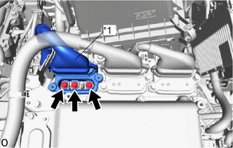
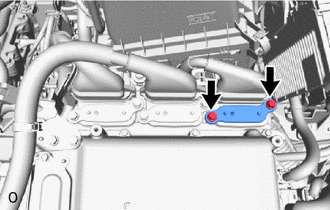
| 8. | CHECK AMD TERMINAL VOLTAGE |
CAUTION:
Be sure to wear insulated gloves.
(a) Connect the cable to the negative (-) auxiliary battery terminal.
| (b) Measure the voltage according to the value(s) in the table below. Standard Voltage:
|
|
(c) Disconnect the cable from the negative (-) auxiliary battery terminal.
| NG | | REPAIR OR REPLACE HARNESS OR CONNECTOR |
|
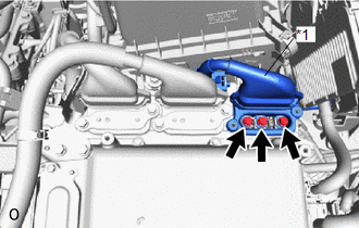
| 9. | CHECK AMD TERMINAL CONNECTION CONDITION |
CAUTION:
Be sure to wear insulated gloves.
(a) Check that the service plug grip is not installed.
NOTICE:
After removing the service plug grip, do not turn the power switch on (READY), unless instructed by the repair manual because this may cause a malfunction.
| (b) Check that the bolts for the AMD terminal are tightened to the specified torque, the AMD terminal is connected securely, and there is no contact problem. Torque: T = 18 N*m {184 kgf*cm, 13 ft.*lbf} (Inverter with converter assembly side) T = 8.4 N*m {86 kgf*cm, 74 in.*lbf} (No. 1 engine room relay block side)
|
| |||||||||||||
| B | | CONNECT SECURELY |
| C | | REPLACE MALFUNCTIONING PARTS |
|
| 10. | CHECK NO. 2 ENGINE ROOM WIRE |
CAUTION:
Be sure to wear insulated gloves.
(a) Check that the service plug grip is not installed.
NOTICE:
After removing the service plug grip, do not turn the power switch on (READY), unless instructed by the repair manual because this may cause a malfunction.
(b) Remove the No. 2 engine room wire from the AMD terminal (inverter with converter assembly side and No. 1 engine room relay block side).
| (c) Measure the resistance according to the value(s) in the table below. Standard Resistance:
|
|
(d) Install the No. 2 engine room wire.
| NG | | REPLACE NO. 2 ENGINE ROOM WIRE |
|
| 11. | CHECK HARNESS AND CONNECTOR (INVERTER WITH CONVERTER ASSEMBLY -D/C D/C-S FUSE) |
CAUTION:
Be sure to wear insulated gloves.
(a) Check that the service plug grip is not installed.
NOTICE:
After removing the service plug grip, do not turn the power switch on (READY), unless instructed by the repair manual because this may cause a malfunction.
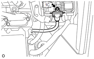
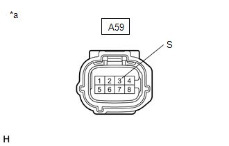
(b) Disconnect the A59 inverter with converter assembly connector.
(c) Connect the cable to the negative (-) auxiliary battery terminal.
| (d) Measure the voltage according to the value(s) in the table below. Standard Voltage:
|
|
(e) Disconnect the cable from the negative (-) auxiliary battery terminal.
(f) Reconnect the A59 inverter with converter assembly connector.
| NG | | REPAIR OR REPLACE HARNESS OR CONNECTOR |
|
| 12. | CHECK HARNESS AND CONNECTOR (RESISTANCE VALUE OF NODD INSIDE HYBRID VEHICLE CONTROL ECU) |
CAUTION:
Be sure to wear insulated gloves.
(a) Check that the service plug grip is not installed.
NOTICE:
After removing the service plug grip, do not turn the power switch on (READY), unless instructed by the repair manual because this may cause a malfunction.
(b) Disconnect the A59 inverter with converter assembly connector.
| (c) Measure the resistance according to the value(s) in the table below. Standard Resistance:
|
|
(d) Reconnect the A59 inverter with converter assembly connector.
| NG | | GO TO STEP 24 |
|
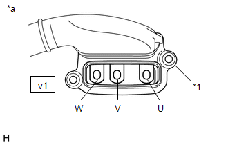
| 13. | CHECK DC/DC CONVERTER FUNCTION |
HINT:
The current at the AMD terminal cannot be measured directly because of space limitations. Measure the current flowing at the auxiliary battery instead.
(a) Connect the AC/DC 400 A probe of the tester to the positive auxiliary battery line.
(b) Install the service plug grip.
(c) Connect the cable to the negative (-) auxiliary battery terminal.
(d) Turn the power switch on (READY) and leave the vehicle as it is until the electric current flowing to the auxiliary battery becomes 10 A or less.
HINT:
If the power switch turns off immediately after it is turned on (READY), auxiliary battery voltage may be low. Recharge the auxiliary battery and perform this procedure again.
(e) Measure the current flowing from the auxiliary battery with the power switch on (READY), the headlight position switch and blower motor switch in the HI position, and the rear window defogger turned on.
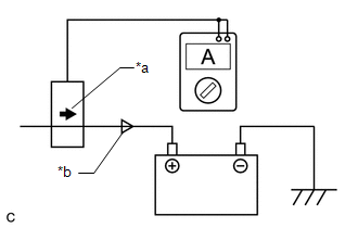
| *a | Probe Direction |
| *b | Current Flowing to Auxiliary Battery |
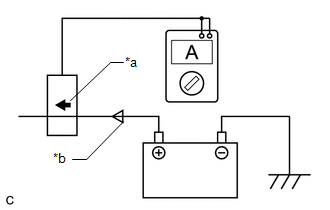
| *a | Probe Direction |
| *b | Current Flowing from Auxiliary Battery |
Standard Current:
| Item | Condition | Specified Condition |
|---|---|---|
| Current flowing from auxiliary battery | Power switch on (READY) (The headlight position switch and blower motor switch are in the HI position, and the rear window defogger is turned on.) | 0 A or less (no current from auxiliary battery) |
(f) Measure the voltage according to the value(s) in the table below.
Standard Voltage:
| Item | Condition | Specified Condition |
|---|---|---|
| A59-3 (S) - Body ground | Power switch on (READY) (The headlight position switch and blower motor switch are in the HI position, and the rear window defogger is turned on.) | Same as auxiliary battery voltage |
(g) Turn the power switch off.
| NG | | REPLACE INVERTER WITH CONVERTER ASSEMBLY |
|
| 14. | CHECK QUANTITY OF HV COOLANT |
Click here
| Result | Proceed to |
|---|---|
| No leaks are found and the HV coolant level in the inverter reserve tank assembly is above the low line. | A |
| No leaks are found and the HV coolant level in the inverter reserve tank assembly is below the low line. | B |
| HV coolant leaks are evident. | C |
| B | | ADD HV COOLANT |
| C | | INSPECT FOR HV COOLANT LEAK AND ADD HV COOLANT |
|
| 15. | CHECK COOLANT HOSE |
Click here
| NG | | REPAIR OR REPLACE COOLANT HOSE |
|
| 16. | PERFORM ACTIVE TEST USING TECHSTREAM (CONTROL THE ELECTRIC COOLING FAN) |
Click here
| NG | | CHECK COOLING FAN SYSTEM |
|
| 17. | CHECK HV COOLANT (CHECK FOR CONDITIONS THAT MAY HAVE CAUSED FREEZING) |
(a) Connect the Techstream to the DLC3
(b) Turn the power switch on (IG).
(c) Enter the following menus: Powertrain / Hybrid Control / Trouble Codes.
(d) Read the freeze frame data item Ambient Temperature using the Techstream.
Powertrain > Hybrid Control > Trouble Codes(e) Check if the freeze frame data item Ambient Temperature is below the freezing temperature of the HV coolant.
| Result | Proceed to |
|---|---|
| Ambient Temperature value is above freezing temperature of the HV coolant. | A |
| Ambient Temperature value is below freezing temperature of the HV coolant. | B |
HINT:
- HV coolant (SLLC) with a 30% concentration freezes at -15°C (5°F) and HV coolant (SLLC) with a 50% concentration freezes at -35°C (-31°F).
- If the HV coolant freezes in the inverter radiator or inverter water pump, the coolant temperature in the inverter with converter assembly rises because the HV coolant cannot circulate. As a result, a DTC may be stored.
- A DTC is stored when the inverter water pump impeller cannot rotate due to freezing of the HV coolant.
- If a DTC is stored due to freezing of the HV coolant, the problem cannot be reproduced. Judge whether freezing of the HV coolant occurred according to the freeze point of the HV coolant, HV coolant change history and ambient temperature when the DTC was stored.
(f) Turn the power switch off.
| A | | REPLACE INVERTER WITH CONVERTER ASSEMBLY |
| B | | REPLACE HV COOLANT |
| 18. | CHECK HARNESS AND CONNECTOR (INVERTER WITH CONVERTER ASSEMBLY - FUSIBLE LINK BLOCK ASSEMBLY) |
CAUTION:
Be sure to wear insulated gloves.
(a) Check that the service plug grip is not installed.
NOTICE:
After removing the service plug grip, do not turn the power switch on (READY), unless instructed by the repair manual because this may cause a malfunction.
(b) Remove the D/C D/C-S fuse from the fuse block assembly.
(c) Disconnect the Q41 fusible link block assembly.
(d) Measure the resistance according to the value(s) in the table below.
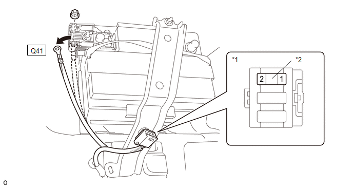
| *1 | Fuse Block Assembly | *2 | D/C D/C-S fuse |
Standard Resistance:
| Tester Connection | Condition | Specified Condition |
|---|---|---|
| 1 (D/C D/C-S fuse terminals) or Q41-1 - Body ground | Power switch off | 10 kΩ or higher |
(e) Install the D/C D/C-S fuse.
(f) Reconnect the Q41 fusible link block assembly connector.
| OK | | REPLACE FUSIBLE LINK BLOCK ASSEMBLY (R/B RR-B) |
| NG | | GO TO STEP 25 |
| 19. | CHECK HARNESS AND CONNECTOR (INVERTER WITH CONVERTER ASSEMBLY - FUSIBLE LINK BLOCK ASSEMBLY) |
CAUTION:
Be sure to wear insulated gloves.
(a) Check that the service plug grip is not installed.
NOTICE:
After removing the service plug grip, do not turn the power switch on (READY), unless instructed by the repair manual because this may cause a malfunction.
(b) Remove the D/C D/C-S fuse from the fuse block assembly.
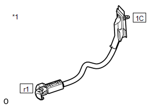
(c) Disconnect the A59 inverter with converter assembly connector.
Click here
(d) Measure the resistance according to the value(s) in the table below.
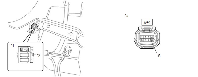
| *1 | Fuse Block Assembly | *2 | D/C D/C-S fuse |
| *a | Front view of wire harness connector (to Inverter with Converter Assembly) | - | - |
Standard Resistance:
| Tester Connection | Condition | Specified Condition |
|---|---|---|
| 2 (D/C D/C-S fuse terminals) or A59-3 (S) - Body ground and other terminals | Power switch off | 10 kΩ or higher |
(e) Reconnect the A59 inverter with converter assembly connector.
(f) Install the D/C D/C-S fuse.
| NG | | GO TO STEP 26 |
|
| 20. | REPLACE INVERTER WITH CONVERTER ASSEMBLY |
Click here
| NEXT | | REPLACE FUSE (D/C D/C-S) |
| 21. | CHECK HYBRID VEHICLE TRANSAXLE ASSEMBLY (GENERATOR (MG1)) |
CAUTION:
Be sure to wear insulated gloves.
(a) Check that the service plug grip is not installed.
NOTICE:
After removing the service plug grip, do not turn the power switch on (READY), unless instructed by the repair manual because this may cause a malfunction.
| (b) Remove the inverter cover UPR from the inverter with converter assembly. |
|
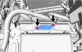
| (c) Disconnect the generator cable from the inverter with converter assembly. |
|
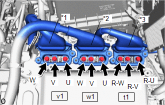
| (d) Using a megohmmeter set to 500 V, measure the insulation resistance according to the value(s) in the table below. NOTICE: Be sure to set the megohmmeter to 500 V when performing this test. Using a setting higher than 500 V can result in damage to the component being inspected. Standard Resistance:
|
|
(e) Connect the generator cable.
(f) Install the inverter cover UPR.
| NG | | REPLACE HYBRID VEHICLE TRANSAXLE ASSEMBLY |
|
| 22. | CHECK HYBRID VEHICLE TRANSAXLE ASSEMBLY (MOTOR (MG2)) |
CAUTION:
Be sure to wear insulated gloves.
(a) Check that the service plug grip is not installed.
NOTICE:
After removing the service plug grip, do not turn the power switch on (READY), unless instructed by the repair manual because this may cause a malfunction.
| (b) Remove the inverter cover UPR from the inverter with converter assembly. |
|
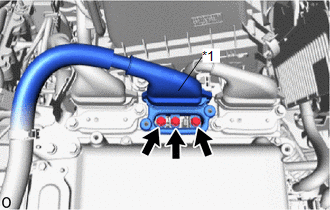
| (c) Disconnect the motor cable from the inverter with converter assembly. |
|
| (d) Using a megohmmeter set to 500 V, measure the insulation resistance according to the value(s) in the table below. NOTICE: Be sure to set the megohmmeter to 500 V when performing this test. Using a setting higher than 500 V can result in damage to the component being inspected. Standard Resistance:
|
|
(e) Connect the motor cable.
(f) Install the inverter cover UPR.
| NG | | REPLACE HYBRID VEHICLE TRANSAXLE ASSEMBLY |
|
| 23. | CHECK REAR TRACTION MOTOR WITH TRANSAXLE ASSEMBLY (REAR MOTOR (MGR)) |
CAUTION:
Be sure to wear insulated gloves.
(a) Check that the service plug grip is not installed.
NOTICE:
After removing the service plug grip, do not turn the power switch on (READY), unless instructed by the repair manual because this may cause a malfunction.
| (b) Remove the inverter cover UPR from the inverter with converter assembly. |
|
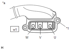
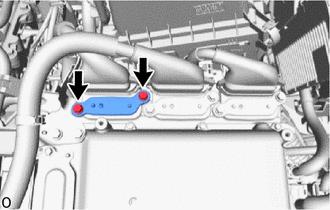
| (c) Disconnect the No. 2 frame wire (rear motor cable) from the inverter with converter assembly. |
|
| (d) Using a megohmmeter set to 500 V, measure the insulation resistance according to the value(s) in the table below. NOTICE: Be sure to set the megohmmeter to 500 V when performing this test. Using a setting higher than 500 V can result in damage to the component being inspected. Standard Resistance:
|
|

(e) Connect the No. 2 frame wire (rear motor cable).
(f) Install the inverter cover UPR.
| OK | | REPLACE INVERTER WITH CONVERTER ASSEMBLY |
| NG | | GO TO STEP 27 |
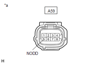
| 24. | INSPECT HYBRID VEHICLE CONTROL ECU (RESISTANCE VALUE OF NODD INSIDE HYBRID VEHICLE CONTROL ECU) |
| (a) Disconnect the A60, A61, I115 and I116 hybrid vehicle control ECU connectors. |
|
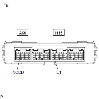
(b) Measure the resistance according to the value(s) in the table below.
Standard Resistance:
| Tester Connection | Condition | Specified Condition |
|---|---|---|
| A60-25 (NODD) - I115-6 (E1) | Power switch off | 110 to 150 kΩ |
(c) Reconnect the A60, A61, I115 and I116 hybrid vehicle control ECU connectors.
| OK | | REPAIR OR REPLACE HARNESS OR CONNECTOR |
| NG | | REPLACE HYBRID VEHICLE CONTROL ECU |
| 25. | REPAIR OR REPLACE HARNESS OR CONNECTOR |
| NEXT | | REPLACE FUSIBLE LINK BLOCK ASSEMBLY (R/B RR-B) |
| 26. | REPAIR OR REPLACE HARNESS OR CONNECTOR |
| NEXT | | REPLACE FUSE (D/C D/C-S) |
| 27. | CHECK REAR TRACTION MOTOR WITH TRANSAXLE ASSEMBLY (NO. 2 FRAME WIRE (REAR MOTOR CABLE) CONNECTION CONDITION) |
CAUTION:
Be sure to wear insulated gloves.
(a) Check that the service plug grip is not installed.
NOTICE:
After removing the service plug grip, do not turn the power switch on (READY), unless instructed by the repair manual because this may cause a malfunction.
| (b) Check that the bolts for the No. 2 frame wire (rear motor cable) are tightened to the specified torque, the No. 2 frame wire (rear motor cable) is connected securely, and there are no contact problems. Specified Condition: T = 15 N*m (153 kgf*cm, 11 ft.*lbf) NOTICE: Make sure that the tightening torque of the bolt is between 12 and 18 N*m (122 and 184 kgf*cm, 9 and 13 ft.*lbf). |
|
(c) Disconnect the No. 2 frame wire (rear motor cable) from the rear traction motor with transaxle assembly
(d) Check for arc marks at the bolts for the No. 2 frame wire (rear motor cable).
| Result | Proceed to | |
|---|---|---|
| The terminals are connected securely and there are no contact problems. | There are no arc marks. | A |
| The terminals are not connected securely and there is a contact problem. | There are arc marks. | B |
| The terminals are not connected securely and there is a contact problem. | There are no arc marks. | C |
| The terminals are connected securely and there are no contact problems. | There are arc marks. | B |
(e) Connect the No. 2 frame wire (rear motor cable).
| B | | REPLACE MALFUNCTIONING PARTS |
| C | | CONNECT SECURELY |
|
| 28. | CHECK NO. 2 FRAME WIRE (REAR MOTOR CABLE) |
CAUTION:
Be sure to wear insulated gloves.
(a) Check that the service plug grip is not installed.
NOTICE:
After removing the service plug grip, do not turn the power switch on (READY), unless instructed by the repair manual because this may cause a malfunction.
(b) Disconnect the No. 2 frame wire (rear motor cable) from the inverter with converter assembly.
| (c) Using a megohmmeter set to 500 V, measure the resistance according to the value(s) in the table below. NOTICE: Be sure to set the megohmmeter to 500 V when performing this test. Using a setting higher than 500 V can result in damage to the component being inspected. Standard Resistance:
NOTICE: Wrap the terminals of No. 2 frame wire (rear motor cable) with insulating tape to avoid them coming into contact with body ground. |
|
(d) Connect the No. 2 frame wire (rear motor cable) to the inverter with converter assembly.
| NG | | REPLACE NO. 2 FRAME WIRE |
|
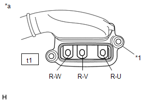
| 29. | CHECK EXTENSION WIRE ASSEMBLY |
CAUTION:
Be sure to wear insulated gloves.
(a) Check that the service plug grip is not installed.
NOTICE:
After removing the service plug grip, do not turn the power switch on (READY), unless instructed by the repair manual because this may cause a malfunction.
(b) Remove the extension wire assembly from the rear traction motor with transaxle assembly.
Click here
| (c) Using a megohmmeter set to 500 V, measure the resistance according to the value(s) in the table below. NOTICE: Be sure to set the megohmmeter to 500 V when performing this test. Using a setting higher than 500 V can result in damage to the component being inspected. Standard Resistance:
|
|
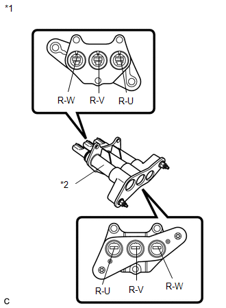
(d) Measure the resistance according to the value(s) in the table below.
Standard Resistance:
| Tester Connection | Condition | Specified Condition |
|---|---|---|
| R-W - R-W | Power switch off | Below 1 Ω |
| R-V - R-V | Power switch off | Below 1 Ω |
| R-U - R-U | Power switch off | Below 1 Ω |
| R-W - R-U | Power switch off | 100 kΩ or higher |
| R-V - R-W | Power switch off | 100 kΩ or higher |
| R-U - R-V | Power switch off | 100 kΩ or higher |
(e) Install the extension wire.
| OK | | REPLACE REAR TRACTION MOTOR WITH TRANSAXLE ASSEMBLY |
| NG | | REPLACE EXTENSION WIRE ASSEMBLY |
READ NEXT:
 DC / DC Converter Status Circuit Low Input (P0A09-265)
DESCRIPTION Refer to the description for DTC P0A08-264. Click here The hybrid vehicle control ECU sends a signal to the DC/DC converter to prohibit its control and receives signals indicating a nor
DC / DC Converter Status Circuit Low Input (P0A09-591)
DESCRIPTION The DC/DC converter varies output voltage based on voltage change signals (VLO signal line) received from the hybrid vehicle control ECU. If the vehicle is being driven with an inoperative
High Voltage System Inter-Lock Circuit High (P0A0D-350,P0A0D-351)
DTC SUMMARY MALFUNCTION DESCRIPTION The hybrid vehicle control ECU detects that a safety device (interlock) is operated or that there is an open circuit in the detection circuit. (Even if an open circ
SEE MORE:
Installation
INSTALLATION CAUTION / NOTICE / HINT NOTICE:
Do not replace the spiral with sensor cable sub-assembly with the battery connected and the engine switch on (IG).
Do not rotate the spiral with sensor cable sub-assembly when the following conditions are met: 1) The steering wheel is removed, 2) the
Diagnostic Trouble Code Chart
DIAGNOSTIC TROUBLE CODE CHART Panoramic View Monitor System DTC No. Detection Item Link C1614 ECU Malfunction C1621 Back Camera Power Supply Failure C1622 Open or Short Circuit in Back Camera Signal C1625 Open or Short in Steering Angle Sensor +B
© 2016-2026 Copyright www.lexunx.com
