Lexus NX: Diagnosis System
DIAGNOSIS SYSTEM
DESCRIPTION
(a) Automatic high beam system data and Diagnostic Trouble Codes (DTCs) can be read from the Data Link Connector 3 (DLC3) of the vehicle. When the system seems to be malfunctioning, use the Techstream to check for malfunctions and to repair it.
CHECK DLC3
(a) Check the DLC3.
Click here .gif)
INSPECT AUXILIARY BATTERY VOLTAGE
(a) Measure the auxiliary battery voltage with the power switch off.
Standard voltage:
11 to 14 V
If the voltage is below 11 V, recharge or replace the auxiliary battery.
DIAGNOSIS SYSTEM
(a) If the automatic high beam system malfunctions, the automatic high beam indicator light turns off and "Headlight System Malfunction Visit Your Dealer" is displayed on the multi-information display.
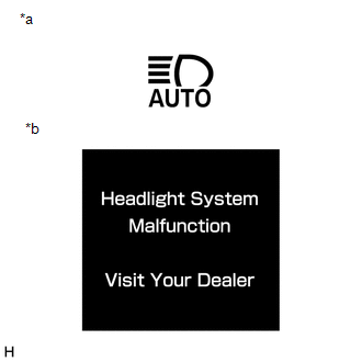
| *a | Automatic High Beam Indicator Light |
| *b | Multi-information Display |
HINT:
When the system returns to normal, "Headlight System Malfunction Visit Your Dealer" is no longer displayed on the multi-information display.
READ NEXT:
 Dtc Check / Clear
DTC CHECK / CLEAR CHECK DTC (a) Connect the Techstream to the DLC3. (b) Turn the power switch on (IG). (c) Turn the Techstream on. (d) Enter the following menus: Body Electrical / Main Body / Trouble
Fail-safe Chart
FAIL-SAFE CHART AUTOMATIC HIGH BEAM SYSTEM (a) The main body ECU (multiplex network body ECU) operates in fail-safe mode if an abnormal condition such as those listed below has been detected. Item
Data List / Active Test
DATA LIST / ACTIVE TEST DATA LIST HINT: Using the Techstream to read the Data List allows the values or states of switches, sensors, actuators and other items to be read without removing any parts. Th
SEE MORE:
Fr Sensor Initialization Incomplete (C1AF3)
DESCRIPTION When it is judged that the front sensors have not been initialized, the clearance warning ECU assembly stores DTC C1AF3. DTC No. Detection Item DTC Detection Condition Trouble Area C1AF3 Fr Sensor Initialization Incomplete Front sensor not initialized
Initialize fro
Control Module Communication Bus OFF (U0073,U0124,U0129,U0293)
DESCRIPTION The parking brake ECU assembly communicates with the hybrid vehicle control ECU, skid control ECU (brake booster with master cylinder assembly) and deceleration sensor (airbag ECU assembly) via CAN communication. DTC No. Detection Item DTC Detection Condition Trouble Area Memo
