Lexus NX: Disassembly
DISASSEMBLY
PROCEDURE
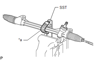
1. FIX STEERING GEAR ASSEMBLY
| (a) Using SST, fix the steering gear assembly. SST: 09612-00012 HINT: Apply protective tape to SST before use. |
|
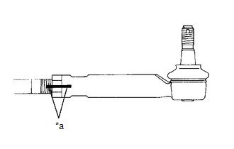
2. REMOVE TIE ROD END SUB-ASSEMBLY LH
| (a) Put matchmarks on the tie rod end sub-assembly LH and rack end. |
|
(b) Remove the tie rod end sub-assembly LH and lock nut.
3. REMOVE TIE ROD END SUB-ASSEMBLY RH
HINT:
Use the same procedure described for the LH side.
4. REMOVE STEERING RACK BOOT CLIP
(a) Using pliers, remove the 2 steering rack boot clips.
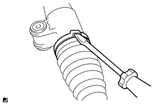
5. REMOVE NO. 2 STEERING RACK BOOT CLAMP
| (a) Using a screwdriver, remove the No. 2 steering rack boot clamp. NOTICE: Be careful not to damage the steering rack boot. |
|
6. REMOVE NO. 1 STEERING RACK BOOT CLAMP
HINT:
Use the same procedure described for the No. 2 steering rack boot clamp.
7. REMOVE NO. 2 STEERING RACK BOOT
(a) Remove the No. 2 steering rack boot.
8. REMOVE NO. 1 STEERING RACK BOOT
(a) Remove the No. 1 steering rack boot.
READ NEXT:
 Inspection
INSPECTION CAUTION / NOTICE / HINT NOTICE:
When using a vise, place aluminum plates between the part and vise.
When using a vise, do not overtighten it.
PROCEDURE 1. INSPECT TIE ROD END SUB-AS
Reassembly
REASSEMBLY PROCEDURE 1. INSTALL NO. 2 STEERING RACK BOOT (a) Apply lithium soap base glycol grease to the inside of the steering rack end. *1 Rack Housing *2 Steering Rack End
Installation
INSTALLATION PROCEDURE 1. INSTALL STEERING GEAR ASSEMBLY (a) Install the steering gear assembly to the front suspension crossmember with the 2 bolts and 2 nuts. Torque: 110 N·m {1122 kgf·cm, 81 ftÂ
SEE MORE:
Washer Fluid Level Warning Switch Circuit
DESCRIPTION When the volume of washer fluid decreases to below a certain level (when the level warning switch assembly is turned on), the multi-information display warns the driver by displaying a message. WIRING DIAGRAM CAUTION / NOTICE / HINT NOTICE: When replacing the combination meter assembly,
Removal
REMOVAL CAUTION / NOTICE / HINT HINT:
Use the same procedure for the RH and LH sides.
The procedure listed below is for the LH side.
PROCEDURE 1. REMOVE SIDE MUDGUARD SUB-ASSEMBLY LH HINT: When removing the side mudguard sub-assembly LH, if the No. 3 moulding tape (double-sided tape) is diff
