Lexus NX: Inspection
INSPECTION
CAUTION / NOTICE / HINT
NOTICE:
- When using a vise, place aluminum plates between the part and vise.
- When using a vise, do not overtighten it.
PROCEDURE
1. INSPECT TIE ROD END SUB-ASSEMBLY LH
| (a) Secure the tie rod end between aluminum plates in a vise. NOTICE: Do not overtighten the vise. |
|
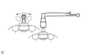
(b) Install the nut to the stud bolt.
(c) Flip the ball joint back and forth 5 times.
(d) Set a torque wrench on the nut, turn the ball joint continuously at a rate of 3 to 5 seconds per turn, and check the turning torque on the 5th turn.
Standard turning torque:
0.98 to 3.92 N*m (10.0 to 39.9 kgf*cm, 8.68 to 34.6 in.*lbf)
If the turning torque is not within the specified range, replace the tie rod end sub-assembly LH with a new one.
2. INSPECT TIE ROD END SUB-ASSEMBLY RH
HINT:
Use the same procedure described for the LH side.
3. INSPECT TOTAL PRELOAD
NOTICE:
Inspect the total preload in a no-load condition by removing the tie rod end sub-assemblies RH and LH, and steering rack boots.
| (a) Install SST to the pinion shaft and turn it left and right 5 times or more. SST: 09616-00011 |
|
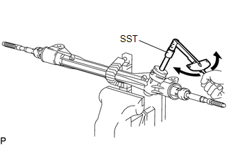
(b) Using a torque wrench and SST, turn the pinion shaft continuously at a rate of 4 to 6 seconds per turn to inspect the total preload of the steering gear assembly.
Total preload:
0.7 to 1.25 N*m (8 to 12 kgf*cm, 7 to 11 in.*lbf)
NOTICE:
Perform the inspection with the steering rack centered.
If the total preload is not within the specified range, replace the steering gear assembly with a new one.
READ NEXT:
 Reassembly
REASSEMBLY PROCEDURE 1. INSTALL NO. 2 STEERING RACK BOOT (a) Apply lithium soap base glycol grease to the inside of the steering rack end. *1 Rack Housing *2 Steering Rack End
Installation
INSTALLATION PROCEDURE 1. INSTALL STEERING GEAR ASSEMBLY (a) Install the steering gear assembly to the front suspension crossmember with the 2 bolts and 2 nuts. Torque: 110 N·m {1122 kgf·cm, 81 ftÂ
SEE MORE:
Dtc Check / Clear
DTC CHECK / CLEAR CHECK DTC (a) Connect the Techstream to the DLC3. (b) Turn the power switch on (IG). (c) Turn the Techstream on. (d) Enter the following menus: Body Electrical / Air Conditioner / Trouble Codes. Body Electrical > Air Conditioner > Trouble Codes (e) Check for DTCs. CLEAR DTC (
Steering Angle Sensor
ComponentsCOMPONENTS ILLUSTRATION *A w/o Steering Heater *B w/ Steering Heater *1 STEERING SENSOR *2 SPIRAL CABLE SUB-ASSEMBLY RemovalREMOVAL PROCEDURE 1. REMOVE SPIRAL W/SENSOR CABLE SUB-ASSEMBLY Click here 2. REMOVE STEERING SENSOR (a) Disengage the 6 claws and 2 pi
