Lexus NX: ECM Power Source Circuit
DESCRIPTION
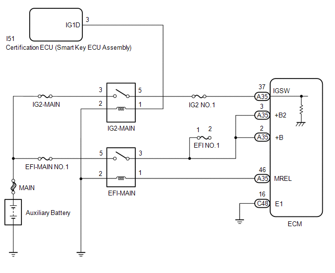
When the power switch is turned on (IG), auxiliary battery voltage is applied to the IGSW terminal of the ECM. The output signal from the MREL terminal of the ECM causes current to flow to the coil of the EFI-MAIN relay, closing the contacts of the EFI-MAIN relay and supplying power to terminals +B and +B2 of the ECM.
WIRING DIAGRAM
CAUTION / NOTICE / HINT
NOTICE:
Inspect the fuses for circuits related to this system before performing the following procedure.
PROCEDURE
| 1. | CHECK HARNESS AND CONNECTOR (IG2-MAIN RELAY VOLTAGE) |
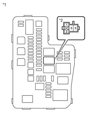
| *1 | No. 1 Engine Room Relay Block and Junction Block Assembly |
| *2 | IG2-MAIN Relay |
(a) Remove the IG2-MAIN relay from the No. 1 engine room relay block and junction block assembly.
(b) Turn the power switch on (IG).
(c) Measure the voltage according to the value(s) in the table below.
Standard Voltage:
| Tester Connection | Condition | Specified Condition |
|---|---|---|
| 1 (IG2-MAIN relay) - Body ground | Power switch on (IG) | 11 to 14 V |
| NG | .gif) | GO TO STEP 11 |
|
.gif)
| 2. | INSPECT IG2-MAIN RELAY |
(a) Inspect the IG2-MAIN relay.
Click here .gif)
| NG | | REPLACE IG2-MAIN RELAY |
|
| 3. | CHECK HARNESS AND CONNECTOR (AUXILIARY BATTERY - IG2-MAIN RELAY) |
| *1 | No. 1 Engine Room Relay Block and Junction Block Assembly |
| *2 | IG2-MAIN Relay |
(a) Remove the IG2-MAIN relay from the No. 1 engine room relay block and junction block assembly.
(b) Measure the voltage according to the value(s) in the table below.
Standard Voltage:
| Tester Connection | Condition | Specified Condition |
|---|---|---|
| 3 (IG2-MAIN relay) - Body ground | Always | 11 to 14 V |
| NG | | REPAIR OR REPLACE HARNESS OR CONNECTOR |
|
| 4. | CHECK HARNESS AND CONNECTOR (IG2-MAIN RELAY - BODY GROUND) |
(a) Remove the IG2-MAIN relay from the No. 1 engine room relay block and junction block assembly.
(b) Measure the resistance according to the value(s) in the table below.
Standard Resistance:
| Tester Connection | Condition | Specified Condition |
|---|---|---|
| 2 (IG2-MAIN relay) - Body ground | Always | Below 1 Ω |
| NG | | REPAIR OR REPLACE HARNESS OR CONNECTOR |
|
| 5. | CHECK HARNESS AND CONNECTOR (IG2-MAIN RELAY - ECM) |
(a) Remove the IG2-MAIN relay from the No. 1 engine room relay block and junction block assembly.
(b) Disconnect the ECM connector.
(c) Measure the resistance according to the value(s) in the table below.
Standard Resistance:
| Tester Connection | Condition | Specified Condition |
|---|---|---|
| 5 (IG2-MAIN relay) - A35-37 (IGSW) | Always | Below 1 Ω |
| 5 (IG2-MAIN relay) or A35-37 (IGSW) - Body ground | Always | 10 kΩ or higher |
| NG | | REPAIR OR REPLACE HARNESS OR CONNECTOR |
|
| 6. | INSPECT EFI-MAIN RELAY |
(a) Inspect the EFI-MAIN relay.
Click here
| NG | | REPLACE EFI-MAIN RELAY |
|
| 7. | CHECK HARNESS AND CONNECTOR (AUXILIARY BATTERY - EFI-MAIN RELAY) |
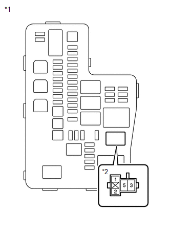
| *1 | No. 1 Engine Room Relay Block and Junction Block Assembly |
| *2 | EFI-MAIN Relay |
(a) Remove the EFI-MAIN relay from the No. 1 engine room relay block and junction block assembly.
(b) Measure the voltage according to the value(s) in the table below.
Standard Voltage:
| Tester Connection | Condition | Specified Condition |
|---|---|---|
| 5 (EFI-MAIN relay) - Body ground | Always | 11 to 14 V |
| NG | | REPAIR OR REPLACE HARNESS OR CONNECTOR |
|
| 8. | CHECK HARNESS AND CONNECTOR (EFI-MAIN RELAY - BODY GROUND) |
(a) Remove the EFI-MAIN relay from the No. 1 engine room relay block and junction block assembly.
(b) Measure the resistance according to the value(s) in the table below.
Standard Resistance:
| Tester Connection | Condition | Specified Condition |
|---|---|---|
| 2 (EFI-MAIN relay) - Body ground | Always | Below 1 Ω |
| NG | | REPAIR OR REPLACE HARNESS OR CONNECTOR |
|
| 9. | CHECK HARNESS AND CONNECTOR (EFI-MAIN RELAY - ECM) |
(a) Remove the EFI-MAIN relay from the No. 1 engine room relay block and junction block assembly.
(b) Disconnect the ECM connector.
(c) Measure the resistance according to the value(s) in the table below.
Standard Resistance:
| Tester Connection | Condition | Specified Condition |
|---|---|---|
| 3 (EFI-MAIN relay) - A35-2 (+B) | Always | Below 1 Ω |
| 3 (EFI-MAIN relay) - A35-3 (+B2) | Always | Below 1 Ω |
| 1 (EFI-MAIN relay) - A35-46 (MREL) | Always | Below 1 Ω |
| 3 (EFI-MAIN relay) or A35-2 (+B) - Body ground | Always | 10 kΩ or higher |
| 3 (EFI-MAIN relay) or A35-3 (+B2) - Body ground | Always | 10 kΩ or higher |
| 1 (EFI-MAIN relay) or A35-46 (MREL) - Body ground | Always | 10 kΩ or higher |
| NG | | REPAIR OR REPLACE HARNESS OR CONNECTOR |
|
| 10. | CHECK HARNESS AND CONNECTOR (ECM - BODY GROUND) |
(a) Disconnect the ECM connector.
(b) Measure the resistance according to the value(s) in the table below.
Standard Resistance:
| Tester Connection | Condition | Specified Condition |
|---|---|---|
| C48-16 (E1) - Body ground | Always | Below 1 Ω |
| OK | | PROCEED TO NEXT SUSPECTED AREA SHOWN IN PROBLEM SYMPTOMS TABLE |
| NG | | REPAIR OR REPLACE HARNESS OR CONNECTOR |
| 11. | CHECK HARNESS AND CONNECTOR (CERTIFICATION ECU (SMART KEY ECU ASSEMBLY) - IG2-MAIN RELAY) |
(a) Disconnect the Certification ECU (smart key ECU assembly) connector.
(b) Remove the IG2-MAIN relay from the No. 1 engine room relay block and junction block assembly.
(c) Measure the resistance according to the value(s) in the table below.
Standard Resistance:
| Tester Connection | Condition | Specified Condition |
|---|---|---|
| I51-3 (IG1D) - 1 (IG2-MAIN relay) | Always | Below 1 Ω |
| OK | | GO TO SMART ACCESS SYSTEM WITH PUSH-BUTTON START |
| NG | | REPAIR OR REPLACE HARNESS OR CONNECTOR |
READ NEXT:
 VC Output Circuit
DESCRIPTION The ECM constantly generates 5 V power source voltage from the auxiliary battery voltages supplied to the +B (BATT) terminal to operate the microprocessor. The ECM also provides this power
Fuel Pump Control Circuit
DESCRIPTION The fuel pump circuit consists of the ECM, fuel pump and fuel pump control ECU assembly (which operates the fuel pump). Based on the engine output, the ECM determines the fuel pump speed.
Fuel Injector Circuit
DESCRIPTION The fuel injector assemblies are located on the intake port. They inject fuel into the cylinders based on the signals from the ECM. WIRING DIAGRAM CAUTION / NOTICE / HINT NOTICE: Inspect
SEE MORE:
Inspection
INSPECTION PROCEDURE 1. INSPECT POWER BACK DOOR SENSOR ASSEMBLY LH (a) Measure the resistance according to the value(s) in the table below. Standard Resistance: Tester Connection Condition Specified Condition 1 (OSL) - 2 (OSLE) Not pressed 950 to 1050 Ω 1 (OSL) - 2 (OSLE) P
Removal
REMOVAL PROCEDURE 1. REMOVE REAR SEAT ASSEMBLY (for Manual Seat) Click here 2. REMOVE REAR SEAT ASSEMBLY (for Power Seat) Click here 3. REMOVE TONNEAU COVER ASSEMBLY Click here 4. REMOVE DECK BOARD ASSEMBLY Click here 5. REMOVE NO. 2 DECK BOARD SUB-ASSEMBLY Click here 6. REMOVE
