Lexus NX: Disassembly
DISASSEMBLY
PROCEDURE
1. REMOVE HEADLIGHT WASHER ACTUATOR SUB-ASSEMBLY RH (w/ Headlight Cleaner System)
Click here .gif)
2. REMOVE HEADLIGHT WASHER ACTUATOR SUB-ASSEMBLY LH (w/ Headlight Cleaner System)
HINT:
Use the same procedure described for the RH side.
3. REMOVE HEADLIGHT CLEANER WASHER NOZZLE COVER RH (w/ Headlight Cleaner System)
Click here
4. REMOVE HEADLIGHT CLEANER WASHER NOZZLE COVER LH (w/ Headlight Cleaner System)
HINT:
Use the same procedure described for the RH side.
5. REMOVE NO. 2 HEADLIGHT CLEANER HOSE (w/ Headlight Cleaner System)
Click here
6. REMOVE HEADLIGHT CLEANER WASHER BRACKET (w/ Headlight Cleaner System)
Click here
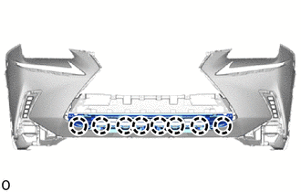
7. REMOVE NO. 3 ENGINE ROOM WIRE
(a) Disconnect the millimeter wave radar sensor connector.
(b) w/ Intuitive Parking Assist System:
Disconnect the 4 connectors.
(c) w/ Panoramic View Monitor System:
Disconnect the connector.
(d) w/o Intuitive Parking Assist System:
Detach the 6 clamps and remove the No. 3 engine room wire.
(e) w/ Intuitive Parking Assist System:
Detach the 12 clamps and remove the No. 3 engine room wire.
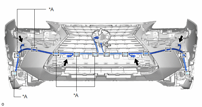
| *A | w/o Intuitive Parking Assist System | - | - |
.png) | w/ Intuitive Parking Assist System | .png) | Millimeter Wave Radar Sensor Connector |
.png) | w/ Panoramic View Monitor System | - | - |
8. REMOVE FRONT CORNER ULTRASONIC SENSOR (w/ Intuitive Parking Assist System)
Click here
9. REMOVE FRONT CORNER ULTRASONIC SENSOR RETAINER (w/ Intuitive Parking Assist System)
Click here
10. REMOVE FRONT CENTER ULTRASONIC SENSOR (w/ Intuitive Parking Assist System)
Click here
11. REMOVE CLEARANCE LIGHT ASSEMBLY LH
(a) for LED Type Turn Signal Light:
Click here
(b) for Bulb Type Turn Signal Light:
Click here
12. REMOVE CLEARANCE LIGHT ASSEMBLY RH
HINT:
Use the same procedure described for the LH side.
13. REMOVE FOG LIGHT ASSEMBLY LH
Click here
14. REMOVE FOG LIGHT ASSEMBLY RH
HINT:
Use the same procedure described for the LH side.
15. REMOVE FRONT BUMPER NO. 2 RETAINER BRACKET
| (a) Remove the 3 screws. |
|
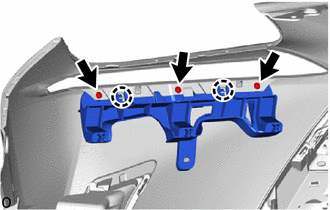
(b) Detach the 2 claws and remove the front bumper No. 2 retainer bracket.
16. REMOVE FRONT BUMPER NO. 1 RETAINER BRACKET
HINT:
Use the same procedure described for the front bumper No. 2 retainer bracket.
17. REMOVE AIR INTAKE DUCT LH
| (a) Remove the 2 clips. |
|
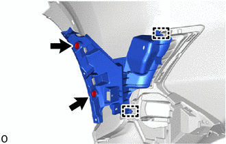
(b) Detach the 2 guides and remove the air intake duct LH.
18. REMOVE AIR INTAKE DUCT RH
HINT:
Use the same procedure described for the LH side.
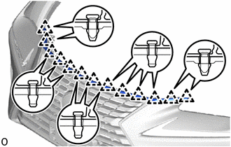
19. REMOVE HOOD TO FRONT END PANEL SEAL
| (a) Detach the 13 clips and remove the hood to front end panel seal. |
|
20. REMOVE RADIATOR GRILLE SUB-ASSEMBLY
Click here
21. REMOVE LOWER RADIATOR GRILLE
| (a) Detach the 8 claws and remove the lower radiator grille. |
|
22. REMOVE NO. 2 RADIATOR GRILLE GARNISH
(a) Using screwdriver, remove the retainer.
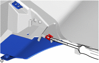
.png) | Protective Tape |
HINT:
Tape the screwdriver tip before use.
(b) Remove the screw.
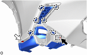
| | Screw |
| | Clip |
(c) Remove the clip.
(d) Detach the 6 claws and guide and remove the No. 2 radiator grille garnish.
23. REMOVE RADIATOR GRILLE GARNISH
HINT:
Use the same procedure described for the No. 2 radiator grille garnish.
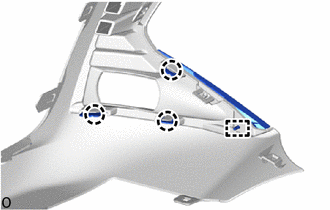
24. REMOVE FOG LIGHT BRACKET LH
| (a) Detach the 3 claws, guide and remove the fog light bracket LH. |
|
25. REMOVE FOG LIGHT BRACKET RH
HINT:
Use the same procedure described for the LH side.
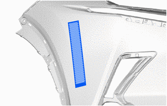
26. REMOVE NO. 2 MOULDING TAPE
HINT:
- When removing the No. 2 moulding tape, heat the front bumper cover and No. 2 moulding tape using a heat light.
- Use the same procedure described for the other side.
Standard:
| Item | Temperature |
|---|---|
| Front Bumper Cover | 20 to 30°C (68 to 86°F) |
| No. 2 Moulding Tape | 20 to 30°C (68 to 86°F) |
NOTICE:
Do not heat the front bumper cover and No. 2 moulding tape excessively.
| (a) Remove the No. 2 moulding tape. |
|
READ NEXT:
 Reassembly
REASSEMBLY PROCEDURE 1. INSTALL NO. 2 MOULDING TAPE HINT:
When installing the No. 2 moulding tape, heat the front bumper cover and No. 2 moulding tape using a heat light.
Use the same procedure d
Installation
INSTALLATION CAUTION / NOTICE / HINT HINT: A bolt without a torque specification is shown in the standard bolt chart. Click here PROCEDURE 1. INSTALL FRONT BUMPER SIDE RETAINER LH (a) Attach the
SEE MORE:
Precaution
PRECAUTION PRECAUTION FOR DISCONNECTING CABLE FROM NEGATIVE AUXILIARY BATTERY TERMINAL NOTICE:
After turning the power switch off, waiting time may be required before disconnecting the cable from the negative (-) auxiliary battery terminal. Therefore, make sure to read the disconnecting the cable
How To Proceed With Troubleshooting
CAUTION / NOTICE / HINT HINT:
Use this procedure to troubleshoot the seat belt warning system.
*: Use the Techstream.
PROCEDURE 1. VEHICLE BROUGHT TO WORKSHOP
NEXT 2. CUSTOMER PROBLEM ANALYSIS HINT:
In troubleshooting, confirm that the problem symptoms h
