Lexus NX: Reassembly
REASSEMBLY
PROCEDURE
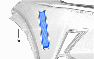
1. INSTALL NO. 2 MOULDING TAPE
HINT:
- When installing the No. 2 moulding tape, heat the front bumper cover and No. 2 moulding tape using a heat light.
- Use the same procedure described for the other side.
Standard:
| Item | Temperature |
|---|---|
| Front Bumper Cover | 20 to 30°C (68 to 86°F) |
| No. 2 Moulding Tape | 20 to 30°C (68 to 86°F) |
NOTICE:
Do not heat the front bumper cover and No. 2 moulding tape excessively.
(a) Clean the front bumper cover surface.
(1) Using a heat light, heat the front bumper cover surface.
(2) Remove the double-sided tape from the front bumper cover.
(3) Wipe off any tape adhesive residue with cleaner.
| (b) Install a new No. 2 moulding tape. (1) Using a heat light, heat the front bumper cover and No. 2 moulding tape. (2) Remove the peeling paper from the face of the No. 2 moulding tape. HINT: After removing the peeling paper, keep the exposed adhesive free from foreign matter. (3) Align the No. 2 moulding tape with the scribed line on the front bumper cover and install it as shown in the illustration. HINT: Press the No. 2 moulding tape firmly to install it. |
|
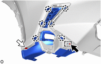
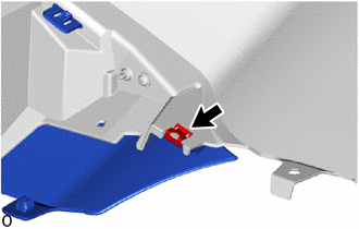
2. INSTALL FOG LIGHT BRACKET LH
| (a) Attach the 3 claws and guide to install the fog light bracket LH. |
|
.png)
3. INSTALL FOG LIGHT BRACKET RH
HINT:
Use the same procedure described for the LH side.
4. INSTALL NO. 2 RADIATOR GRILLE GARNISH
(a) Attach the 6 claws and guide to install the No. 2 radiator grille garnish.
.png) | Screw |
 | Clip |
(b) Install the clip.
(c) Install the screw.
| (d) Install the retainer. |
|
5. INSTALL RADIATOR GRILLE GARNISH
HINT:
Use the same procedure described for the No. 2 radiator grille garnish.
6. INSTALL LOWER RADIATOR GRILLE
| (a) Attach the 8 claws to install the lower radiator grille. |
|
.png)
7. INSTALL RADIATOR GRILLE SUB-ASSEMBLY
Click here .gif)
8. INSTALL HOOD TO FRONT END PANEL SEAL
| (a) Attach the 13 clips to install the hood to front end panel seal. |
|
.png)
9. INSTALL AIR INTAKE DUCT LH
| (a) Attach the 2 guides to install the air intake duct LH. |
|
.png)
(b) Install the 2 clips.
10. INSTALL AIR INTAKE DUCT RH
HINT:
Use the same procedure described for the LH side.
11. INSTALL FRONT BUMPER NO. 2 RETAINER BRACKET
| (a) Attach the 2 claws to install the front bumper No. 2 retainer bracket. |
|
.png)
(b) Install the 3 screws.
12. INSTALL FRONT BUMPER NO. 1 RETAINER BRACKET
HINT:
Use the same procedure described for the front bumper No. 2 retainer bracket.
13. INSTALL FOG LIGHT ASSEMBLY LH
Click here
14. INSTALL FOG LIGHT ASSEMBLY RH
HINT:
Use the same procedure described for the LH side.
15. INSTALL CLEARANCE LIGHT ASSEMBLY LH
(a) for LED Type Turn Signal Light:
Click here
(b) for Bulb Type Turn Signal Light:
Click here
16. INSTALL CLEARANCE LIGHT ASSEMBLY RH
HINT:
Use the same procedure described for the LH side.
17. INSTALL FRONT CENTER ULTRASONIC SENSOR (w/ Intuitive Parking Assist System)
Click here
18. INSTALL FRONT CORNER ULTRASONIC SENSOR RETAINER (w/ Intuitive Parking Assist System)
Click here
19. INSTALL FRONT CORNER ULTRASONIC SENSOR (w/ Intuitive Parking Assist System)
Click here
20. INSTALL NO. 3 ENGINE ROOM WIRE
(a) w/ Intuitive Parking Assist System:
Attach the 12 clamps to install the No. 3 engine room wire.
.png)
| *A | w/o Intuitive Parking Assist System | - | - |
| | w/ Intuitive Parking Assist System | .png) | Millimeter Wave Radar Sensor Connector |
.png) | w/ Panoramic View Monitor System | - | - |
(b) w/o Intuitive Parking Assist System:
Attach the 6 clamps to install the No. 3 engine room wire.
(c) w/ Panoramic View Monitor System:
Connect the connector.
(d) w/ Intuitive Parking Assist System:
Connect the 4 connectors.
(e) Connect the millimeter wave radar sensor connector.
21. INSTALL HEADLIGHT CLEANER WASHER BRACKET (w/ Headlight Cleaner System)
Click here
22. INSTALL NO. 2 HEADLIGHT CLEANER HOSE (w/ Headlight Cleaner System)
Click here
23. INSTALL HEADLIGHT CLEANER WASHER NOZZLE COVER RH (w/ Headlight Cleaner System)
Click here
24. INSTALL HEADLIGHT CLEANER WASHER NOZZLE COVER LH (w/ Headlight Cleaner System)
HINT:
Use the same procedure described for the RH side.
25. INSTALL HEADLIGHT WASHER ACTUATOR SUB-ASSEMBLY RH (w/ Headlight Cleaner System)
Click here
26. INSTALL HEADLIGHT WASHER ACTUATOR SUB-ASSEMBLY LH (w/ Headlight Cleaner System)
HINT:
Use the same procedure described for the RH side.
READ NEXT:
 Installation
INSTALLATION CAUTION / NOTICE / HINT HINT: A bolt without a torque specification is shown in the standard bolt chart. Click here PROCEDURE 1. INSTALL FRONT BUMPER SIDE RETAINER LH (a) Attach the
Components
COMPONENTS ILLUSTRATION *1 FRONT BUMPER ASSEMBLY *2 FRONT FENDER FRONT SPLASH SHIELD LH *3 FRONT FENDER FRONT SPLASH SHIELD RH *4 RADIATOR GRILLE PROTECTOR *5 RADIATOR SUPPOR
SEE MORE:
Front Occupant Classification Sensor LH Circuit Malfunction (B1780)
DESCRIPTION The front occupant classification sensor LH circuit consists of the occupant detection ECU and front occupant classification sensor LH. DTC B1780 is stored when a malfunction is detected in the front occupant classification sensor LH circuit. DTC No. Detection Item DTC Detection C
Fuel information
You must only use unleaded gasoline
in your vehicle.
Select octane rating 87 (Research
Octane Number 91) or higher. Use
of unleaded gasoline with an octane
rating lower than 87 may result in
engine knocking. Persistent knocking
can lead to engine damage.
At minimum, the gasoline you use
s
