Lexus NX: Installation
INSTALLATION
CAUTION / NOTICE / HINT
HINT:
A bolt without a torque specification is shown in the standard bolt chart.
Click here .gif)
PROCEDURE
1. INSTALL FRONT BUMPER SIDE RETAINER LH
| (a) Attach the 2 claws to install the front bumper side retainer LH. |
|
(b) Attach the clip.
(c) Install the 2 screws.
2. INSTALL FRONT BUMPER SIDE RETAINER RH
HINT:
Use the same procedure described for the LH side.
3. INSTALL FRONT BUMPER REINFORCEMENT SUB-ASSEMBLY
| (a) Install the front bumper reinforcement sub-assembly with the 6 bolts. Torque: 34 N·m {347 kgf·cm, 25 ft·lbf} |
|
.png)
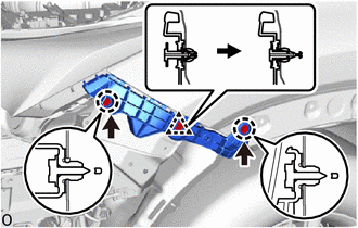
4. INSTALL FRONT BUMPER SIDE MOUNTING BRACKET ASSEMBLY LH
| (a) Install the front bumper side mounting bracket assembly LH with the 6 bolts. Torque: 50 N·m {510 kgf·cm, 37 ft·lbf} |
|
.png)
5. INSTALL FRONT BUMPER ENERGY ABSORBER
| (a) Install the front bumper energy absorber. |
|
.png)
6. INSTALL FRONT BUMPER ASSEMBLY
(a) w/ Intuitive Parking Assist System:
Connect the 2 No. 3 engine room wire connectors.
(b) w/o Intuitive Parking Assist System:
Connect the No. 3 engine room wire connector.
(c) Connect the 2 clearance light connectors.
(d) Connect the 2 fog light connectors.
(e) w/ Headlight Cleaner System:
(1) Connect the headlight washer hose.
HINT:
Confirm that the headlight washer hose is not twisted.
(f) Attach the 10 claws to install the front bumper assembly.
.png)
| (g) Install the 2 bolts. |
|
.png)
| (h) Install the 2 clips. |
|
.png)
(i) Remove the protective tape.
| (j) Install the 4 bolts. |
|
.png)
7. INSTALL FRONT FENDER FRONT SPLASH SHIELD LH
| (a) Install the front fender front splash shield LH with the 5 screws. |
|
.png)
8. INSTALL FRONT FENDER FRONT SPLASH SHIELD RH
HINT:
Use the same procedure described for the LH side.
9. INSTALL NO. 1 MOULDING TAPE (for Front Fender)
Click here
10. INSTALL NO. 2 MOULDING TAPE (for Front Fender)
Click here
11. INSTALL FRONT FENDER MOULDING SUB-ASSEMBLY LH (for Front Fender)
Click here
12. INSTALL FRONT FENDER MOULDING SUB-ASSEMBLY RH (for Front Fender)
HINT:
Use the same procedure described for the LH side.
13. INSTALL RADIATOR GRILLE PROTECTOR
.png)
(a) Install the 2 radiator grille protectors.
14. INSTALL RADIATOR SUPPORT OPENING COVER
.png)
(a) Install the radiator support opening cover with the 10 clips.
15. ADD WINDSHIELD WASHER FLUID (w/ Headlight Cleaner System)
Click here
16. ADJUST FOG LIGHT AIMING
Click here
17. ADJUST FRONT TELEVISION CAMERA ASSEMBLY (w/ Panoramic View Monitor System)
Click here
HINT:
When only the front bumper assembly is removed and reinstalled, it is not necessary to adjust the front television camera assembly (Such as when removing or installing the front bumper in order to remove or install the headlight assembly).
18. PERFORM CALIBRATION (w/ Intelligent Clearance Sonar System)
Click here
READ NEXT:
 Components
COMPONENTS ILLUSTRATION *1 FRONT BUMPER ASSEMBLY *2 FRONT FENDER FRONT SPLASH SHIELD LH *3 FRONT FENDER FRONT SPLASH SHIELD RH *4 RADIATOR GRILLE PROTECTOR *5 RADIATOR SUPPOR
Removal
REMOVAL CAUTION / NOTICE / HINT HINT: When the front bumper is damaged or deformed due to an accident or contact with other objects, etc., or the bumper installation area on the body is repaired, it i
SEE MORE:
Installation
INSTALLATION PROCEDURE 1. INSTALL HEATER ACCESSORY ASSEMBLY (a) Connect the heater water inlet hose A with the paint mark (Blue) facing up and attach the clip within the area shown in the illustration. NOTICE: Do not apply excessive force to the heater water inlet hose A. *a View A
Diagnostic Trouble Code Chart
DIAGNOSTIC TROUBLE CODE CHART Airbag System DTC No. Detection Item Link B1000 Airbag ECU Malfunction B1610 Front Airbag Sensor (RH) B1612 Front Airbag Sensor Lost Communication (RH) B1613 Front Airbag Sensor Initialization Error (RH) B1615 Fro
