Lexus NX: Disassembly
DISASSEMBLY
PROCEDURE
1. REMOVE HEADLIGHT WASHER ACTUATOR SUB-ASSEMBLY RH (w/ Headlight Cleaner System)
Click here .gif)
2. REMOVE HEADLIGHT WASHER ACTUATOR SUB-ASSEMBLY LH (w/ Headlight Cleaner System)
HINT:
Use the same procedure described for the RH side.
3. REMOVE HEADLIGHT CLEANER WASHER NOZZLE COVER RH (w/ Headlight Cleaner System)
Click here
4. REMOVE HEADLIGHT CLEANER WASHER NOZZLE COVER LH (w/ Headlight Cleaner System)
HINT:
Use the same procedure described for the RH side.
5. REMOVE NO. 2 HEADLIGHT CLEANER HOSE (w/ Headlight Cleaner System)
Click here
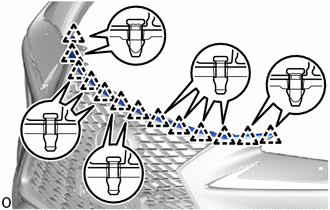
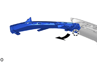
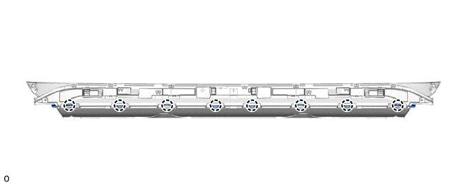
6. REMOVE NO. 3 ENGINE ROOM WIRE
(a) Disconnect the millimeter wave radar sensor connector.
(b) w/ Intuitive Parking Assist System:
Disconnect the 4 connectors.
(c) w/ Panoramic View Monitor System:
Disconnect the connector.
(d) w/o Intuitive Parking Assist System:
Detach the 7 clamps and remove the No. 3 engine room wire.
(e) w/ Intuitive Parking Assist System:
Detach the 16 clamps and remove the No. 3 engine room wire.
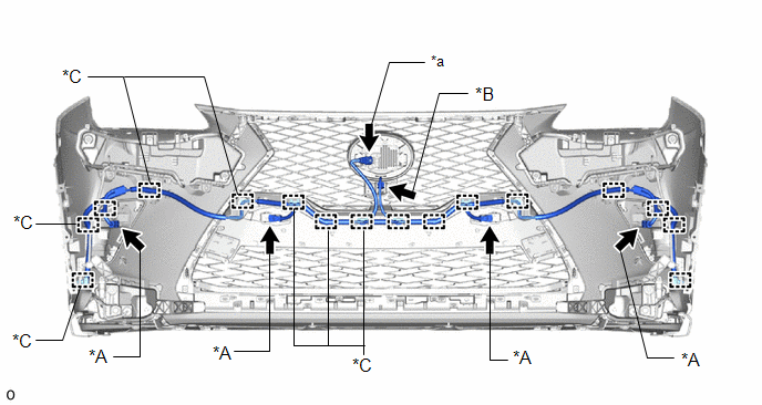
| *A | w/ Intuitive Parking Assist System | *B | w/ Panoramic View Monitor System |
| *C | w/o Intuitive Parking Assist System | - | - |
| *a | Millimeter Wave Radar Sensor Connector | - | - |
7. REMOVE FRONT CORNER ULTRASONIC SENSOR (w/ Intuitive Parking Assist System)
Click here
8. REMOVE FRONT CENTER ULTRASONIC SENSOR (w/ Intuitive Parking Assist System)
Click here
9. REMOVE CLEARANCE LIGHT ASSEMBLY LH
Click here
10. REMOVE CLEARANCE LIGHT ASSEMBLY RH
HINT:
Use the same procedure described for the LH side.
11. REMOVE FOG LIGHT ASSEMBLY LH
Click here
12. REMOVE FOG LIGHT ASSEMBLY RH
HINT:
Use the same procedure described for the LH side.
13. REMOVE FRONT BUMPER NO. 2 RETAINER BRACKET
| (a) Remove the 3 screws. |
|
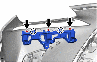
(b) Detach the 2 claws and remove the front bumper No. 2 retainer bracket.
14. REMOVE FRONT BUMPER NO. 1 RETAINER BRACKET
HINT:
Use the same procedure described for the front bumper No. 2 retainer bracket.
15. REMOVE AIR INTAKE DUCT LH
| (a) Remove the 2 clips. |
|
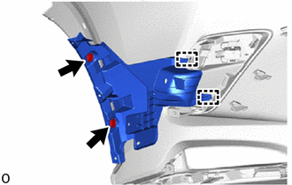
(b) Detach the 2 guides and remove the air intake duct LH.
16. REMOVE AIR INTAKE DUCT RH
HINT:
Use the same procedure described for the LH side.
17. REMOVE NO. 2 RADIATOR GRILLE GARNISH
(a) Remove the 4 outside moulding retainers.
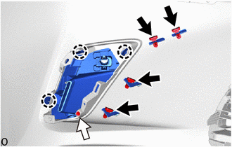
.png) | Outside Moulding Retainer |
.png) | Screw |
(b) Remove the screw.
(c) Detach the 3 claws and remove the No. 2 radiator grille garnish.
18. REMOVE RADIATOR GRILLE GARNISH
HINT:
Use the same procedure described for the No. 2 radiator grille garnish.
19. REMOVE HOOD TO FRONT END PANEL SEAL
| (a) Detach the 13 clips and remove the hood to front end panel seal. |
|
20. REMOVE FRONT BUMPER GUARD ASSEMBLY
(a) Detach the 6 clips and 3 screws.
(b) Detach the 13 claws and remove the front bumper guard assembly.
| | Screw | | Clip |
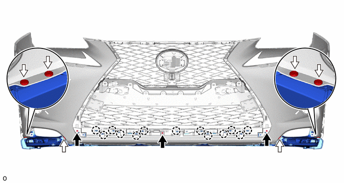
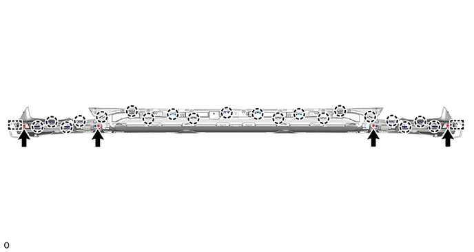
21. REMOVE FRONT BUMPER NO. 2 GUARD
(a) Remove the 4 screws.
(b) Detach the 20 claws, 2 guides and remove the front bumper No. 2 guard.
22. REMOVE FRONT BUMPER NO. 2 GUARD PAD LH
(a) Use a screwdriver to remove the retainer.
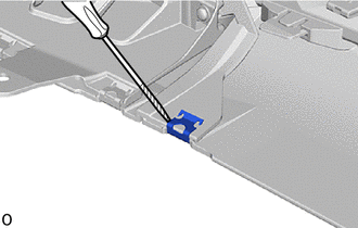
.png) | Protective Tape |
HINT:
Tape the screwdriver tip before use.
| (b) Detach the claw and remove the front bumper No. 2 guard pad LH. |
|
23. REMOVE FRONT BUMPER NO. 2 GUARD PAD RH
HINT:
Use the same procedure described for the LH side.
24. REMOVE FRONT BUMPER GUARD
(a) Detach the 8 claws and remove the front bumper guard.
25. REMOVE LOWER RADIATOR GRILLE MOULDING
26. REMOVE RADIATOR GRILLE SUB-ASSEMBLY
Click here
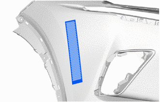
27. REMOVE NO. 2 MOULDING TAPE
HINT:
- When removing the No. 2 moulding tape, heat the front bumper cover and No. 2 moulding tape using a heat light.
- Use the same procedure described for the other side.
Standard:
| Item | Temperature |
|---|---|
| Front Bumper Cover | 20 to 30°C (68 to 86°F) |
| No. 2 Moulding Tape | 20 to 30°C (68 to 86°F) |
NOTICE:
Do not heat the front bumper cover and No. 2 moulding tape excessively.
| (a) Remove the No. 2 moulding tape. |
|
READ NEXT:
 Reassembly
REASSEMBLY PROCEDURE 1. INSTALL NO. 2 MOULDING TAPE HINT:
When installing the No. 2 moulding tape, heat the front bumper cover and No. 2 moulding tape using a heat light.
Use the same procedure d
Installation
INSTALLATION CAUTION / NOTICE / HINT HINT: A bolt without a torque specification is shown in the standard bolt chart. Click here PROCEDURE 1. INSTALL FRONT BUMPER SIDE RETAINER LH Click here 2. IN
SEE MORE:
Intake Air Temperature Sensor 1 Circuit Range / Performance (P0111)
DESCRIPTION Refer to DTC P0112. Click here DTC No. Detection Item DTC Detection Condition Trouble Area MIL Memory P0111 Intake Air Temperature Sensor 1 Circuit Range / Performance Either of the following conditions is met (2 trip detection logic):
The change in intake air t
Customize Parameters
CUSTOMIZE PARAMETERS CUSTOMIZE POWER TILT AND POWER TELESCOPIC STEERING COLUMN SYSTEM HINT: The following items can be customized. NOTICE:
When the customer requests a change in a function, first make sure that the function can be customized.
Record the current settings before customizing.
(
