Lexus NX: Reassembly
REASSEMBLY
PROCEDURE
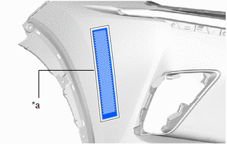
1. INSTALL NO. 2 MOULDING TAPE
HINT:
- When installing the No. 2 moulding tape, heat the front bumper cover and No. 2 moulding tape using a heat light.
- Use the same procedure described for the other side.
Standard:
| Item | Temperature |
|---|---|
| Front Bumper Cover | 20 to 30°C (68 to 86°F) |
| No. 2 Moulding Tape | 20 to 30°C (68 to 86°F) |
NOTICE:
Do not heat the front bumper cover and No. 2 moulding tape excessively.
(a) Clean the front bumper cover surface.
(1) Using a heat light, heat the front bumper cover surface.
(2) Remove the double-sided tape from the front bumper cover.
(3) Wipe off any tape adhesive residue with cleaner.
| (b) Install a new No. 2 moulding tape. (1) Using a heat light, heat the front bumper cover and No. 2 moulding tape. (2) Remove the peeling paper from the face of the No. 2 moulding tape. HINT: After removing the peeling paper, keep the exposed adhesive free from foreign matter. (3) Align the No. 2 moulding tape with the scribed line on the front bumper cover and install it as shown in the illustration. HINT: Press the No. 2 moulding tape firmly to install it. |
|
2. INSTALL RADIATOR GRILLE SUB-ASSEMBLY
Click here .gif)
3. INSTALL LOWER RADIATOR GRILLE MOULDING
4. INSTALL FRONT BUMPER GUARD
(a) Attach the 8 claws and install the front bumper guard to the lower radiator grille moulding.
.png)
5. INSTALL FRONT BUMPER NO. 2 GUARD PAD LH
| (a) Attach the claw to install the front bumper No. 2 guard pad LH to the lower radiator grille moulding. |
|
(b) Install the retainer.
6. INSTALL FRONT BUMPER NO. 2 GUARD PAD RH
HINT:
Use the same procedure described for the LH side.
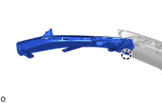
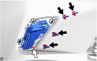
7. INSTALL FRONT BUMPER NO. 2 GUARD
(a) Attach the 20 claws and 2 guides to install the front bumper No. 2 guard.
(b) Install the 4 screws.
.png)
8. INSTALL FRONT BUMPER GUARD ASSEMBLY
(a) Attach the 13 claws and install the front bumper guard assembly.
(b) Install the 6 clips and 3 screws.
.png)
.png) | Screw | .png) | Clip |
9. INSTALL HOOD TO FRONT END PANEL SEAL
| (a) Attach the hood to front end panel seal with the 13 clips. |
|
.png)
10. INSTALL AIR INTAKE DUCT LH
| (a) Attach the 2 guides to install the air intake duct LH. |
|
.png)
(b) Install the 2 clips.
11. INSTALL AIR INTAKE DUCT RH
HINT:
Use the same procedure described for the LH side.
12. INSTALL NO. 2 RADIATOR GRILLE GARNISH
(a) Attach the 3 claws to install the No. 2 radiator grille garnish.
| | Outside Moulding Retainer |
| | Screw |
(b) Install the screw.
(c) Install the 4 outside moulding retainers.
13. INSTALL RADIATOR GRILLE GARNISH
HINT:
Use the same procedure described for the No. 2 radiator grille garnish.
14. INSTALL FRONT BUMPER NO. 2 RETAINER BRACKET
| (a) Attach the 2 claws to install the front bumper No. 2 retainer bracket. |
|
.png)
(b) Install the 3 screws.
15. INSTALL FRONT BUMPER NO. 1 RETAINER BRACKET
HINT:
Use the same procedure described for the front bumper No. 2 retainer bracket.
16. INSTALL FOG LIGHT ASSEMBLY LH
Click here
17. INSTALL FOG LIGHT ASSEMBLY RH
HINT:
Use the same procedure described for the LH side.
18. INSTALL CLEARANCE LIGHT ASSEMBLY LH
Click here
19. INSTALL CLEARANCE LIGHT ASSEMBLY RH
HINT:
Use the same procedure described for the LH side.
20. INSTALL FRONT CORNER ULTRASONIC SENSOR (w/ Intuitive Parking Assist System)
Click here
21. INSTALL FRONT CENTER ULTRASONIC SENSOR (w/ Intuitive Parking Assist System)
Click here
22. INSTALL NO. 3 ENGINE ROOM WIRE
(a) w/ Intuitive Parking Assist System:
Attach the 16 clamps to install the No. 3 engine room wire.
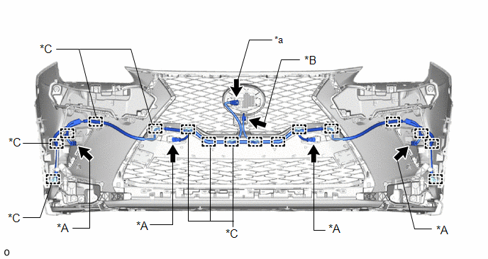
| *A | w/ Intuitive Parking Assist System | *B | w/ Panoramic View Monitor System |
| *C | w/o Intuitive Parking Assist System | - | - |
| *a | Millimeter Wave Radar Sensor Connector | - | - |
(b) w/o Intuitive Parking Assist System:
Attach the 7 clamps and install the No. 3 engine room wire.
(c) w/ Panoramic View Monitor System:
Connect the connector.
(d) w/ Intuitive Parking Assist System:
Connect the 4 connectors.
(e) Connect the millimeter wave radar sensor connector.
23. INSTALL NO. 2 HEADLIGHT CLEANER HOSE (w/ Headlight Cleaner System)
Click here
24. INSTALL HEADLIGHT CLEANER WASHER NOZZLE COVER RH (w/ Headlight Cleaner System)
Click here
25. INSTALL HEADLIGHT CLEANER WASHER NOZZLE COVER LH (w/ Headlight Cleaner System)
HINT:
Use the same procedure described for the RH side.
26. INSTALL HEADLIGHT WASHER ACTUATOR SUB-ASSEMBLY RH (w/ Headlight Cleaner System)
Click here
27. INSTALL HEADLIGHT WASHER ACTUATOR SUB-ASSEMBLY LH (w/ Headlight Cleaner System)
HINT:
Use the same procedure described for the RH side.
READ NEXT:
 Installation
INSTALLATION CAUTION / NOTICE / HINT HINT: A bolt without a torque specification is shown in the standard bolt chart. Click here PROCEDURE 1. INSTALL FRONT BUMPER SIDE RETAINER LH Click here 2. IN
Components
COMPONENTS ILLUSTRATION *1 DECK FLOOR BOX LH *2 NO. 3 DECK BOARD SUB-ASSEMBLY *3 REAR DECK FLOOR BOX *4 NEGATIVE AUXILIARY BATTERY TERMINAL N*m (kgf*cm, ft.*lbf): Specified
SEE MORE:
Installation
INSTALLATION PROCEDURE 1. INSTALL RADIATOR GRILLE SUB-ASSEMBLY (a) Attach the 14 claws and the 4 guides to install the radiator grille sub-assembly. (b) Install the 2 outside moulding retainers. (c) Install the 6 screws. Screw Outside Moulding Retainer 2. INSTALL FRONT BUMPER GUARD AS
EVAP System
RELATED DTCS DTC No. Monitoring Item Link P00FE EVAP vent line blocked P043E Reference orifice clogged (built into canister pump module) P043F Reference orifice high-flow (built into canister pump module) P0441
Purge VSV (Vacuum Switching Valve) stuck clos
