Lexus NX: Installation
INSTALLATION
CAUTION / NOTICE / HINT
HINT:
A bolt without a torque specification is shown in the standard bolt chart.
Click here .gif)
PROCEDURE
1. INSTALL FRONT BUMPER SIDE RETAINER LH
Click here
2. INSTALL FRONT BUMPER SIDE RETAINER RH
HINT:
Use the same procedure described for the LH side.
3. INSTALL FRONT BUMPER REINFORCEMENT SUB-ASSEMBLY
Click here
4. INSTALL FRONT BUMPER SIDE MOUNTING BRACKET ASSEMBLY LH
Click here
5. INSTALL LOWER RADIATOR AIR GUIDE PLATE
| (a) Attach the 2 clips to install the lower radiator air guide plate. |
|
.png)
6. INSTALL FRONT BUMPER LOWER ABSORBER
.png)
(a) Install the front bumper lower absorber with the 8 screws.
7. INSTALL FRONT BUMPER ENERGY ABSORBER
Click here
8. INSTALL FRONT BUMPER ASSEMBLY
(a) w/ Intuitive Parking Assist System:
Connect the 2 No. 3 engine room wire connectors.
(b) w/o Intuitive Parking Assist System:
Connect the No. 3 engine room wire connector.
(c) Connect the 2 clearance light connectors.
(d) Connect the 2 fog light connectors.
(e) w/ Headlight Cleaner System:
(1) Connect the headlight washer hose.
HINT:
Confirm that the headlight washer hose is not twisted.
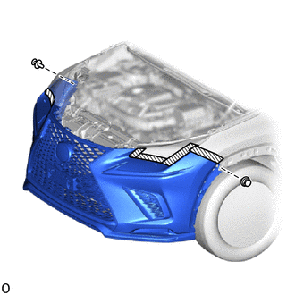
(f) Attach the 10 claws to install the front bumper assembly.
.png)
| (g) Install the 2 bolts. |
|
.png)
(h) Install the 2 clips.
.png) | Protective Tape |
(i) Remove the protective tape.
| (j) Install the 6 screws. |
|
.png)
9. INSTALL FRONT FENDER FRONT SPLASH SHIELD LH
.png)
(a) Install the front fender front splash shield LH with the 5 screws.
10. INSTALL FRONT FENDER FRONT SPLASH SHIELD RH
HINT:
Use the same procedure described for the LH side.
11. INSTALL NO. 1 MOULDING TAPE (for Front Fender)
Click here
12. INSTALL NO. 2 MOULDING TAPE (for Front Fender)
Click here
13. INSTALL FRONT FENDER MOULDING SUB-ASSEMBLY LH (for Front Fender)
Click here
14. INSTALL FRONT FENDER MOULDING SUB-ASSEMBLY RH (for Front Fender)
HINT:
Use the same procedure described for the LH side.
15. INSTALL RADIATOR GRILLE PROTECTOR
| (a) Install the 2 radiator grille protectors. |
|
.png)
16. INSTALL RADIATOR SUPPORT OPENING COVER
| (a) Install the radiator support opening cover with the 10 clips. |
|
.png)
17. ADD WINDSHIELD WASHER FLUID (w/ Headlight Cleaner System)
Click here
18. ADJUST FOG LIGHT AIMING
Click here
19. ADJUST FRONT TELEVISION CAMERA ASSEMBLY (w/ Panoramic View Monitor System)
Click here
HINT:
When only the front bumper assembly is removed and reinstalled, it is not necessary to adjust the front television camera assembly.(Such as when removing or installing the front bumper in order to remove or install the headlight assembly.)
20. PERFORM CALIBRATION (w/ Intelligent Clearance Sonar System)
Click here
READ NEXT:
 Components
COMPONENTS ILLUSTRATION *1 DECK FLOOR BOX LH *2 NO. 3 DECK BOARD SUB-ASSEMBLY *3 REAR DECK FLOOR BOX *4 NEGATIVE AUXILIARY BATTERY TERMINAL N*m (kgf*cm, ft.*lbf): Specified
Removal
REMOVAL CAUTION / NOTICE / HINT HINT:
Use the same procedure for the RH and LH sides.
The procedure listed below is for the LH side.
PROCEDURE 1. PRECAUTION NOTICE: After the power switch off
SEE MORE:
Components
COMPONENTS ILLUSTRATION *A for 2WD *B for AWD *1 HOOD LOCK ASSEMBLY *2 NO. 6 INVERTER BRACKET *3 UPPER RADIATOR SUPPORT SUB-ASSEMBLY *4 FRONT RADIATOR SIDE AIR GUIDE PLATE RH *5 FRONT RADIATOR SIDE AIR GUIDE PLATE LH *6 WIRE HARNESS N*m (kgf*cm, ft.*lbf
Freeze Frame Data
FREEZE FRAME DATA DESCRIPTION (a) When a pre-collision system DTC is stored, the forward recognition camera stores the current vehicle (ECU or sensor) state as Freeze Frame Data. CHECK FREEZE FRAME DATA (a) Connect the Techstream to the DLC3. (b) Turn the power switch on (IG). (c) Turn the Techstrea
