Lexus NX: Disassembly
DISASSEMBLY
CAUTION / NOTICE / HINT
HINT:
- Use the same procedure for the RH and LH sides.
- The procedure listed below is for the LH side.
PROCEDURE
1. REMOVE FRONT ROOF RACK LEG CUSHION LH
| (a) Remove the front roof rack leg cushion LH. |
|
2. REMOVE REAR ROOF RACK LEG CUSHION LH
| (a) Remove the rear roof rack leg cushion LH. |
|
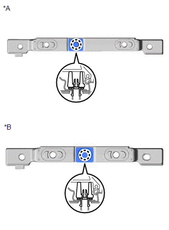
3. REMOVE NO. 2 ROOF CARRIER SEAL
| (a) Remove the No. 2 roof carrier seal. |
|
4. REMOVE NO. 3 ROOF CARRIER SEAL LH
| (a) Remove the No. 3 roof carrier seal LH. |
|
5. REMOVE ROOF CARRIER SEAL
| (a) Remove the roof carrier seal. |
|
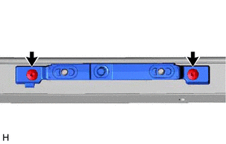
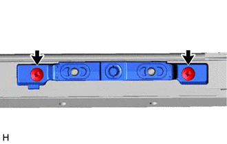
6. REMOVE FRONT ROOF RACK LEG LH
| (a) Using a T30 "TORX" socket wrench, remove the 2 screws and front roof rack leg LH. |
|
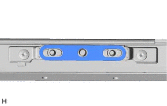
7. REMOVE CENTER ROOF RACK SUPPORT LH
| (a) Using a T30 "TORX" socket wrench, remove the 2 screws and center roof rack support LH. |
|
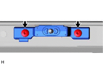
8. REMOVE REAR ROOF RACK LEG LH
| (a) Using a T30 "TORX" socket wrench, remove the 2 screws and rear roof rack leg LH. |
|
9. REMOVE FRONT ROOF RACK RETAINER LH
| (a) Detach the claw and remove the front roof rack retainer LH. |
|
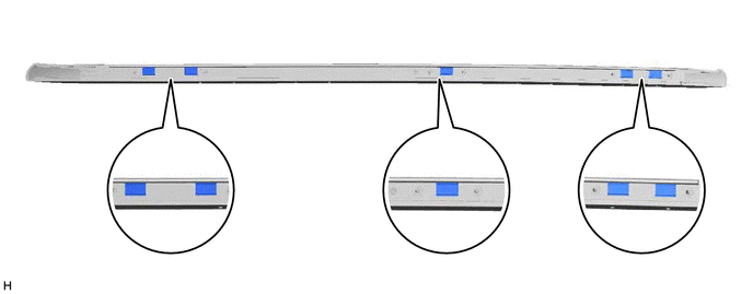
10. REMOVE NO. 1 ROOF CARRIER SEAL
(a) Remove the 5 No. 1 roof carrier seals.
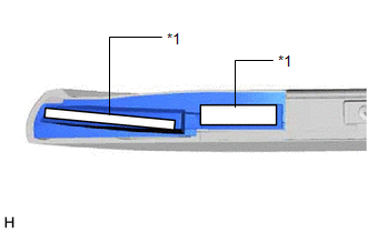
11. REMOVE NO. 1 ROOF CARRIER PROTECTOR
(a) Remove the No. 1 roof carrier protector.
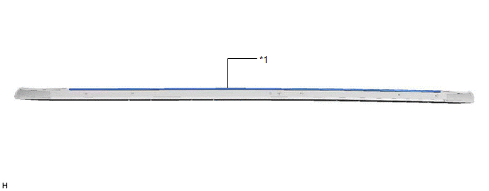
| *1 | No. 1 Roof Carrier Protector | - | - |
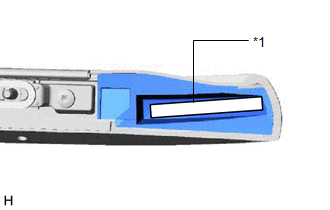
12. REMOVE NO. 2 ROOF CARRIER PROTECTOR
(a) Remove the No. 2 roof carrier protector.
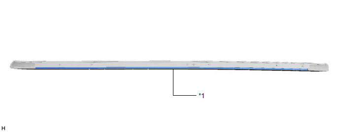
| *1 | No. 2 Roof Carrier Protector | - | - |
READ NEXT:
 Reassembly
REASSEMBLY CAUTION / NOTICE / HINT HINT:
Use the same procedure for the RH and LH sides.
The procedure listed below is for the LH side.
PROCEDURE 1. INSTALL NO. 2 ROOF CARRIER PROTECTOR (a) Cl
Installation
INSTALLATION CAUTION / NOTICE / HINT HINT:
Use the same procedure for the RH and LH sides.
The procedure listed below is for the LH side.
PROCEDURE 1. INSTALL ROOF RACK ASSEMBLY (a) Install th
SEE MORE:
Dtc Check / Clear
DTC CHECK / CLEAR CHECK DTC (a) Turn the power switch off. (b) Connect the Techstream to the DLC3. (c) Turn the power switch on (IG). (d) Turn the Techstream on. (e) Enter the following menus: Body Electrical / SRS Airbag / Trouble Codes. Body Electrical > SRS Airbag > Trouble Codes (f) Check
Multi-information display
The multi-information display presents
the driver with a variety of
vehicle data.
Display and menu icons
■ Display
■ Menu icons
Drive information
Navigation system-linked display
(if equipped)
Audio system-linked
display (if
equipped)
Driving assist system information
Wa
