Lexus NX: Disassembly
DISASSEMBLY
PROCEDURE
1. PRECAUTION
NOTICE:
-
Be sure to read Precaution thoroughly before servicing.
Click here
.gif)
- Do not reuse parts which have reduced fastening ability due to thread damage.
- When installing components, make sure that the wire harness is not pinched or pulled.
- Do not use solvent to clean components. Only clean them with a dry cloth.
HINT:
- Use the same procedure for the RH and LH sides.
- The procedure listed below is for the LH side.
2. REMOVE FRONT SIDE MARKER LIGHT SOCKET
(a) Turn the front side marker light socket counterclockwise until the matchmark is aligned with the unlock position mark to remove it.
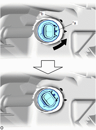
| *a | Matchmark |
| *b | Unlock Position Mark |
.png) | Counterclockwise |
3. REMOVE FRONT SIDE MAKER LIGHT BULB
| (a) Remove the front side marker light bulb from the front side marker light socket. |
|
.png)
4. REMOVE HEADLIGHT ECU SUB-ASSEMBLY LH (w/ Headlight ECU)
Click here
5. REMOVE HEADLIGHT GASKET (w/ Headlight ECU)
Click here
READ NEXT:
 Inspection
INSPECTION PROCEDURE 1. INSPECT HEADLIGHT ASSEMBLY LH (a) Apply battery voltage to the connector and check the light illumination condition. OK: Battery Connection Specified Condition Pos
Adjustment
ADJUSTMENT CAUTION / NOTICE / HINT HINT:
Use the same procedure for the RH and LH sides.
The procedure listed below is for the LH side.
It is possible that a headlight assembly is incorrectly i
Reassembly
REASSEMBLY CAUTION / NOTICE / HINT NOTICE:
Handle components indoors as much as possible to prevent foreign matter from entering and adhering to headlight assembly components.
Do not reuse parts
SEE MORE:
Screen Flicker or Color Distortion
PROCEDURE 1. CHECK DISPLAY SETTING (a) Reset display settings (contrast, brightness) and check that the screen appears normal. OK: The display returns to normal. OK END (DISPLAY SETTING WAS CAUSE OF MALFUNCTION) NG PROCEED TO NEXT SUSPECTED AREA SHOWN IN PROBLEM SYMPTOMS TA
Control Module Communication Bus "A" Off (U0073,U0100,U0124,U0126,U0129,U0140,U0155,U0164,U0293)
DESCRIPTION These DTCs are stored if there is a malfunction in the CAN communication system connected to the clearance warning ECU assembly. HINT: If CAN communication system DTCs are stored, they may also be stored in other systems. DTC No. Detection Item DTC Detection Condition Trouble Ar
© 2016-2026 Copyright www.lexunx.com
