
Lexus NX: Reassembly
REASSEMBLY
CAUTION / NOTICE / HINT
NOTICE:
- Handle components indoors as much as possible to prevent foreign matter from entering and adhering to headlight assembly components.
- Do not reuse parts which have reduced fastening ability due to thread damage.
- When installing components, make sure that the wire harness is not pinched or pulled.
- Do not use solvent to clean components. Only clean them with a dry cloth.
HINT:
- Use the same procedure for the RH and LH sides.
- The procedure listed below is for the LH side.
PROCEDURE
1. INSTALL HEADLIGHT GASKET (w/ Headlight ECU)
Click here .gif)
2. INSTALL HEADLIGHT ECU SUB-ASSEMBLY LH (w/ Headlight ECU)
Click here
3. INSTALL FRONT SIDE MAKER LIGHT BULB
(a) Install the front side marker light bulb to the front side marker light socket.
4. INSTALL FRONT SIDE MARKER LIGHT SOCKET
(a) Align the matchmark of the front side marker light socket to the unlock position mark, and then rotate the front side marker light socket clockwise until the lock position mark to install it.
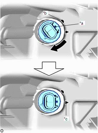
| *a | Matchmark |
| *b | Unlock Position Mark |
| *c | Lock Position Mark |
.png) | Clockwise |
READ NEXT:
 Installation
INSTALLATION CAUTION / NOTICE / HINT HINT:
Use the same procedure for the RH and LH sides.
The procedure described below is for the LH side.
PROCEDURE 1. INSTALL HEADLIGHT ASSEMBLY LH (a) w
Repair
REPAIR CAUTION / NOTICE / HINT HINT:
Use the same procedure for the RH and LH sides.
The procedure listed below is for the LH side.
If the installation area of the headlight assembly is damaged
SEE MORE:
Installation
INSTALLATION CAUTION / NOTICE / HINT CAUTION: As the engine assembly with transaxle is extremely heavy, the engine lifter may suddenly drop if the instructions listed in the repair manual are not followed. Therefore, always follow the instructions listed in the repair manual when performing this pro
EVAP System Tank Vapor Line Restricted/Blocked (P00FE)
DTC SUMMARY DTC No. Detection Item DTC Detection Condition Trouble Area MIL Memory P00FE EVAP System Tank Vapor Line Restricted/Blocked Leak detection pump creates negative pressure (vacuum) in EVAP system and EVAP system pressure is measured. When the fuel level in the fuel tan
© 2016-2026 Copyright www.lexunx.com
