Lexus NX: Reassembly
REASSEMBLY
CAUTION / NOTICE / HINT
HINT:
- Use the same procedure for the RH and LH sides.
- The procedure listed below is for the LH side.
PROCEDURE
1. INSTALL OUTER MIRROR RETRACTOR LH
| (a) Install a new frame sub-assembly with the 2 screws. |
|
.png)
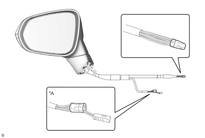
(b) Wind vinyl tape around the harness sub-assembly as shown in the illustration.
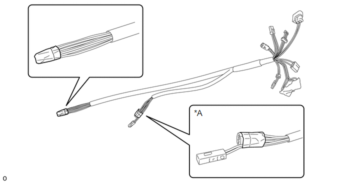
| *A | w/ Memory, w/ Panoramic View Monitor System | - | - |
(c) Pass a new harness sub-assembly through the frame sub-assembly as shown in the illustration.
.png) | Install in this Direction |
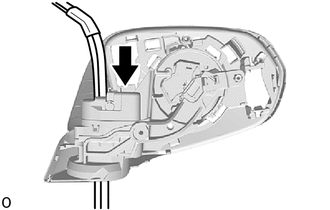
(d) Install the actuator sub-assembly.
.png)
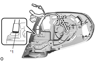
| *1 | Connector Cover |
(1) Connect the 2 connectors and install the connector cover.
| (2) Install the actuator sub-assembly with the 3 screws. |
|
.png)
| (e) Attach the wire harness clamp. |
|
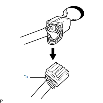
(f) Align the harness sub-assembly with the marking as shown in the illustration.
| (g) Connect the connector and install the connector cover. |
|
.png)
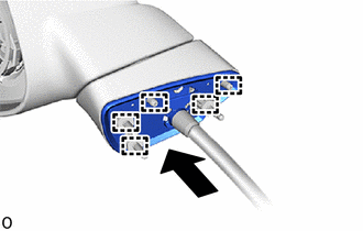
(h) Pass the harness sub-assembly through the base sub-assembly as shown in the illustration.
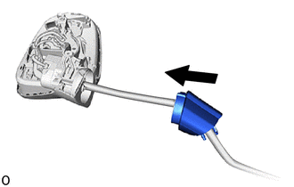
| | Install in this Direction |
| (i) Using a T25 "TORX" socket wrench, install the base sub-assembly with 3 new screws. NOTICE: When installing the base sub-assembly, check that the harness sub-assembly is not caught between the base sub-assembly and body. Failure to do so may cause a short circuit. |
|
.png)
(j) Pass the harness sub-assembly through a new gasket and attach the 5 guides to install the gasket as shown in the illustration.
| | Install in this Direction |
| (k) Align the harness sub-assembly so that the marking is at the position shown in the illustration. |
|
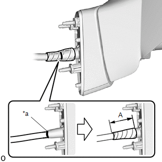
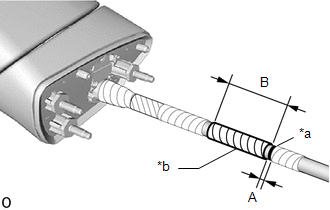
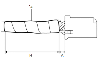
(l) Wind vinyl tape around the harness sub-assembly to secure it as shown in the illustration.
Reference Measurement:
| Area | Measurement |
|---|---|
| A | 50 mm (1.97 in.) |
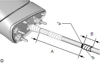
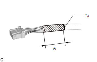
(m) Wind seal D around the harness sub-assembly as shown in the illustration.
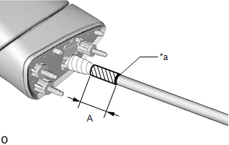
| *a | Marking |
.png) | Seal D |
Reference Measurement:
| Area | Measurement |
|---|---|
| A | 40 mm (1.57 in.) |
| (n) Wind vinyl tape around the harness sub-assembly as shown in the illustration. Reference Measurement:
|
|
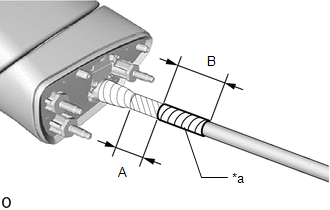
| (o) Wind vinyl tape around the harness sub-assembly as shown in the illustration. Reference Measurement:
|
|
| (p) w/ Panoramic View Monitor System: (1) Wind vinyl tape around the harness sub-assembly as shown in the illustration. Reference Measurement:
|
|
| (q) Attach the 4 claws and install the hook. |
|
.png)
(r) Remove the vinyl tape.
| *A | w/ Memory, w/ Panoramic View Monitor System | - | - |
(s) Connect the each wire harness pin to a new connector.
(1) Set a new retainer to the unlock position.
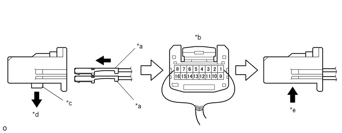
| *a | Wire Harness Pin | *b | Rear View of Connector |
| *c | Retainer | *d | Retainer Unlock Position |
| *e | Retainer Lock Position | - | - |
(2) w/ Memory, w/ Blind Spot Monitor System:
Insert new wire harness pins from the backside of the adapter until they lock.
Wire Harness Color Chart:
| 1 | 2 | 3 | 4 | 5 | 6 | 7 | 8 |
|---|---|---|---|---|---|---|---|
| PURPLE | - | SKY BLUE | BLACK-GREEN | ORANGE | WHITE-BLACK | BLUE-YELLOW | BLACK-WHITE |
Wire Harness Color Chart:
| 9 | 10 | 11 | 12 | 13 | 14 | 15 | 16 |
|---|---|---|---|---|---|---|---|
| BROWN | RED | LIGHT GREEN | WHITE | YELLOW-BLACK | GRAY | BLACK-RED | PINK |
(3) w/ Memory, w/o Blind Spot Monitor System:
Insert new wire harness pins from the backside of the adapter until they lock.
Wire Harness Color Chart:
| 1 | 2 | 3 | 4 | 5 | 6 | 7 | 8 |
|---|---|---|---|---|---|---|---|
| PURPLE | - | SKY BLUE | BLACK-GREEN | ORANGE | WHITE-BLACK | BLUE-YELLOW | - |
Wire Harness Color Chart:
| 9 | 10 | 11 | 12 | 13 | 14 | 15 | 16 |
|---|---|---|---|---|---|---|---|
| BROWN | RED | LIGHT GREEN | WHITE | YELLOW-BLACK | GRAY | BLACK-RED | PINK |
(4) w/o Memory, w/ Panoramic view monitor system:
Insert new wire harness pins from the backside of the adapter until they lock.
Wire Harness Color Chart:
| 1 | 2 | 3 | 4 | 5 | 6 | 7 | 8 |
|---|---|---|---|---|---|---|---|
| PURPLE | - | SKY BLUE | BLACK-GREEN | GREEN | YELLOW | BLUE-WHITE | - |
Wire Harness Color Chart:
| 9 | 10 | 11 | 12 | 13 | 14 | 15 | 16 |
|---|---|---|---|---|---|---|---|
| BROWN | RED | LIGHT GREEN | WHITE | BLUE | BLACK | BLUE-BLACK | PINK |
(5) w/o Memory, w/o Panoramic view monitor system:
Insert new wire harness pins from the backside of the adapter until they lock.
Wire Harness Color Chart:
| 1 | 2 | 3 | 4 | 5 | 6 | 7 | 8 |
|---|---|---|---|---|---|---|---|
| PURPLE | - | SKY BLUE | BLACK-GREEN | - | - | - | - |
Wire Harness Color Chart:
| 9 | 10 | 11 | 12 | 13 | 14 | 15 | 16 |
|---|---|---|---|---|---|---|---|
| BROWN | RED | LIGHT GREEN | WHITE | - | - | - | PINK |
(6) Set the retainer to the lock position.
NOTICE:
- When inserting the pins of the wire harness, compare the new connector with the connector that was cut off during removal and make sure that the arrangement of the wire colors of the pins is the same as before.
- Make sure to insert the wire harness pins at the correct location, as the pins cannot be removed once they are locked.
- Check that the wire harness pins are securely locked and cannot be removed.
(t) w/ Memory:
(1) Wind vinyl sheet around the harness sub-assembly to secure it as shown in the illustration.
| *a | Marking |
| | Vinyl Sheet |
Reference Measurement:
| Area | Measurement |
|---|---|
| A | 55 mm (2.17 in.) |
| (u) Wind vinyl tape around the harness sub-assembly to secure it as shown in the illustration. Reference Measurement:
|
|
(v) w/ Memory, w/ Panoramic View Monitor System:
| (1) Connect each connector to a new adapter. |
|
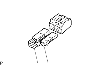
| (2) Route the longer part of the harness sub-assembly as shown in the illustration. |
|
2. INSTALL SIDE TELEVISION CAMERA ASSEMBLY LH (w/ Panoramic View Monitor System)
Click here .gif)
3. INSTALL SIDE TURN SIGNAL LIGHT ASSEMBLY LH
Click here
4. INSTALL OUTER MIRROR LH
Click here
READ NEXT:
 Installation
INSTALLATION CAUTION / NOTICE / HINT HINT:
Use the same procedure for the RH and LH sides.
The procedure listed below is for the LH side.
PROCEDURE 1. INSTALL OUTER REAR VIEW MIRROR ASSEMBLY L
Components
COMPONENTS ILLUSTRATION *1 OUTER MIRROR LH - -
SEE MORE:
Open in One Side of Bus 5 Branch Line
DESCRIPTION When the CAN bus main lines are normal (no open, short to ground, short to +B or short between lines) and there is an ECU or sensor on the "Communication Bus Check" screen that is indicated as not communicating or whose connection status on the "Communication Bus Check" screen changes in
Components
COMPONENTS ILLUSTRATION *A for RH Side - - *1 REAR NO. 1 SEAT HEADREST SUPPORT ASSEMBLY *2 REAR SEAT CUSHION MOULDING RH *3 REAR SEAT CUSHION MOULDING RH *4 REAR SEAT HEADREST ASSEMBLY *5 REAR SEAT INNER WITH CENTER BELT ASSY RH *6 REAR SEATBACK BOARD CARPET A
