Lexus NX: Disassembly
DISASSEMBLY
PROCEDURE
1. REMOVE CHILD RESTRAINT SEAT TETHER ANCHOR COVER
| (a) Detach the 2 claws, 2 guides and remove the child restraint seat tether anchor cover. |
|
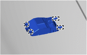
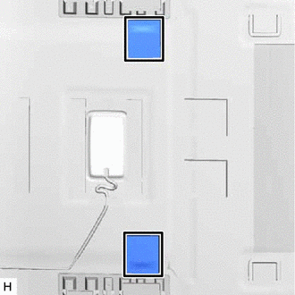
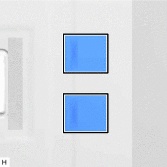
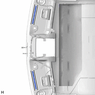
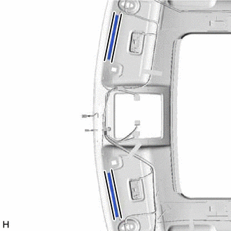
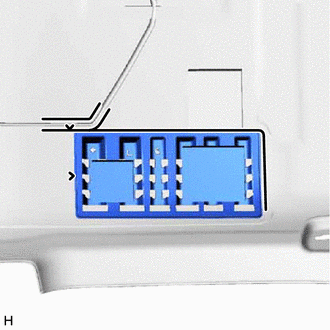
2. REMOVE VANITY LIGHT ASSEMBLY
HINT:
Use the same procedure for both vanity light assemblies..
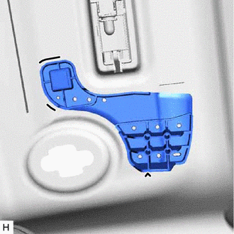
| (a) Detach the 2 claws A and separate the bulb holder from the vanity light assembly as shown in the illustration. |
|
(b) Detach the claw B and remove the vanity light assembly.
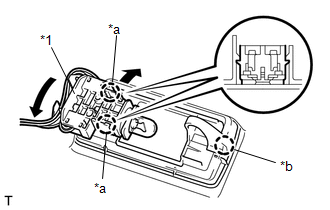
3. REMOVE TELEPHONE MICROPHONE ASSEMBLY
Click here .gif)
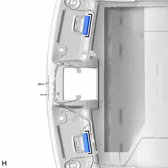
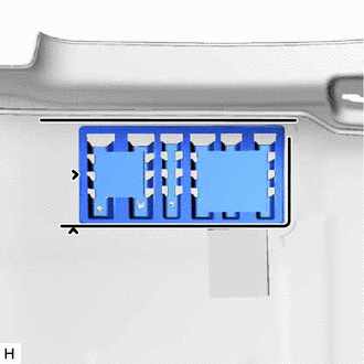
4. REMOVE NO. 1 MICROPHONE CASE
| (a) Detach the claw. |
|
(b) Detach the guide and remove the No. 1 microphone case.
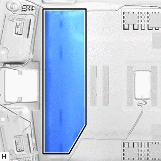
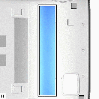
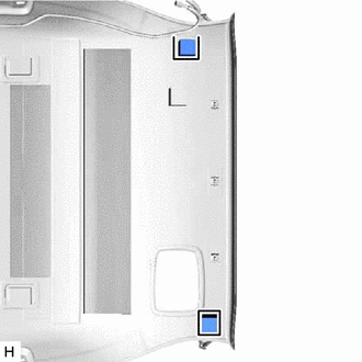
5. REMOVE NO. 1 ROOF SILENCER PAD (for Normal Roof)
| (a) Remove the No. 1 roof silencer pad. |
|
6. REMOVE NO. 2 ROOF SILENCER PAD (for Normal Roof)
| (a) Remove the No. 2 roof silencer pad. |
|
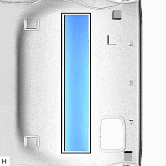
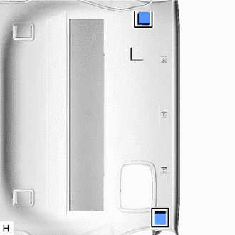
7. REMOVE NO. 3 ROOF SILENCER PAD (for Normal Roof)
| (a) Remove the 2 No. 3 roof silencer pads. |
|
8. REMOVE REAR ROOF SILENCER PAD (for Normal Roof)
| (a) Remove the rear roof silencer pad. |
|
9. REMOVE REAR ROOF SILENCER PAD (for Sliding Roof)
| (a) Remove the rear roof silencer pad. |
|
10. REMOVE NO. 4 ROOF SILENCER PAD (for Normal Roof)
| (a) Remove the No. 4 roof silencer pad. |
|
11. REMOVE ROOF HEADLINING PAD (for Normal Roof)
| (a) Remove the 2 roof headlining pads. |
|
12. REMOVE ROOF HEADLINING PAD (for Sliding Roof)
| (a) Remove the 2 roof headlining pads. |
|
13. REMOVE FRONT ROOF HEADLINING SIDE PAD (for Normal Roof)
| (a) Remove the 2 front roof headlining side pads. |
|
14. REMOVE ROOF HEADLINING END PAD (for Normal Roof)
| (a) Remove the 2 roof headlining end pads. |
|
15. REMOVE ROOF HEADLINING END PAD (for Sliding Roof)
| (a) Remove the 2 roof headlining end pads. |
|
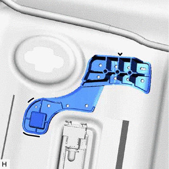
16. REMOVE NO. 2 ROOF HEADLINING SUPPORT (for Normal Roof)
| (a) Remove the No. 2 roof headlining support. |
|
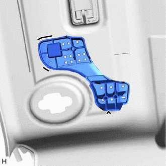
17. REMOVE ROOF HEADLINING SUPPORT (for Normal Roof)
| (a) Remove the roof headlining support. |
|
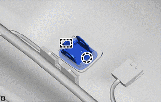
18. REMOVE NO. 1 ROOF WIRE (for Normal Roof)
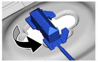
| (a) Turn the visor connectors approximately 90° counterclockwise and remove them from the roof headlining. |
|
(b) Remove each piece of tape and the No. 1 roof wire from the roof headlining.
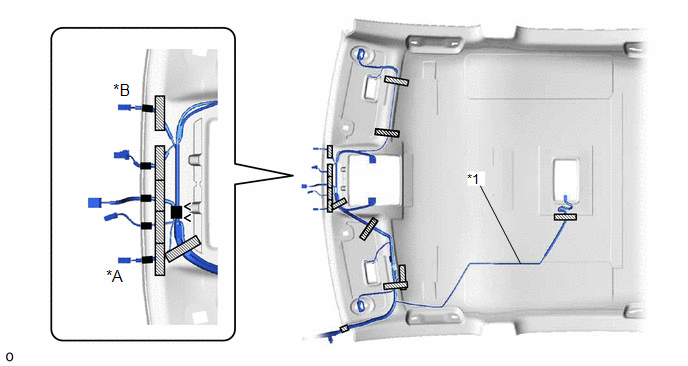
| *A | w/ Humidity Sensor | *B | w/ Rain Sensor |
| *1 | No. 1 Roof Wire | - | - |
.png) | Tape | - | - |
(c) Remove the butyl tape remaining on the roof headlining.
19. REMOVE NO. 1 ROOF WIRE (for Sliding Roof)
| (a) Turn the visor connectors approximately 90° counterclockwise and remove them from the roof headlining. |
|
(b) Remove each piece of tape and the No. 1 roof wire from the roof headlining.
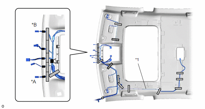
| *A | w/ Humidity Sensor | *B | w/ Rain Sensor |
| *1 | No. 1 Roof Wire | - | - |
| | Tape | - | - |
(c) Remove the butyl tape remaining on the roof headlining.
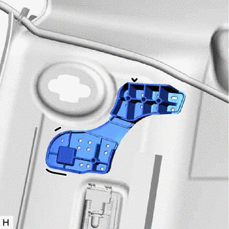
20. REMOVE NO. 4 ROOF HEADLINING SUPPORT (for Normal Roof)
| (a) Remove the No. 4 roof headlining support. |
|
21. REMOVE NO. 3 ROOF HEADLINING SUPPORT (for Normal Roof)
| (a) Remove the No. 3 roof headlining support. |
|
22. REMOVE NO. 4 ROOF HEADLINING SUPPORT (for Sliding Roof)
| (a) Remove the No. 4 roof headlining support. |
|
23. REMOVE NO. 3 ROOF HEADLINING SUPPORT (for Sliding Roof)
| (a) Remove the No. 3 roof headlining support. |
|
24. REMOVE NO. 2 ANTENNA CORD SUB-ASSEMBLY
Click here
READ NEXT:
 Reassembly
REASSEMBLY PROCEDURE 1. INSTALL NO. 2 ANTENNA CORD SUB-ASSEMBLY Click here 2. INSTALL NO. 4 ROOF HEADLINING SUPPORT (for Normal Roof) (a) Align the No. 4 roof headlining support with the marking
Installation
INSTALLATION CAUTION / NOTICE / HINT HINT: A bolt without a torque specification is shown in the standard bolt chart. Click here PROCEDURE 1. INSTALL REAR NO. 2 SIDE RAIL SPACER LH (a) Attach the 2
Tonneau Cover Assembly
ComponentsCOMPONENTS ILLUSTRATION *1 NO. 1 TONNEAU COVER HOLDER CAP *2 TONNEAU COVER CAP PLATE *3 REAR TONNEAU COVER CAP *4 CUSHION *5 STRING - - DisassemblyDISASSEM
SEE MORE:
AUTO Power Retract Mirrors do not operate
DESCRIPTION When the outer mirror switch assembly is set to AUTO (neutral position), an AUTO signal is detected by the main body ECU (multiplex network body ECU). When locking and unlocking all doors with the power switch off, the main body ECU (multiplex network body ECU) sends deploy/retract signa
Back Camera Internal Circuit (C2A63)
DESCRIPTION This DTC is stored when the parking assist ECU detects a signal indicating a malfunction in the rear television camera assembly via CAN communication. DTC No. Detection Item DTC Detection Condition Trouble Area C2A63 Back Camera Internal Circuit A signal indicating a mal
