Lexus NX: Reassembly
REASSEMBLY
PROCEDURE
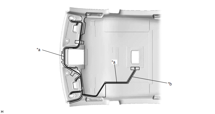
1. INSTALL NO. 2 ANTENNA CORD SUB-ASSEMBLY
Click here .gif)
2. INSTALL NO. 4 ROOF HEADLINING SUPPORT (for Normal Roof)
| (a) Align the No. 4 roof headlining support with the marking on the roof headlining and install the No. 4 roof headlining support using double-sided tape or hot-melt glue as shown in the illustration. |
|
3. INSTALL NO. 3 ROOF HEADLINING SUPPORT (for Normal Roof)
| (a) Align the No. 3 roof headlining support with the marking on the roof headlining and install the No. 3 roof headlining support using double-sided tape or hot-melt glue as shown in the illustration. |
|
4. INSTALL NO. 4 ROOF HEADLINING SUPPORT (for Sliding Roof)
| (a) Align the No. 4 roof headlining support with the marking on the roof headlining and install the No. 4 roof headlining support using double-sided tape or hot-melt glue as shown in the illustration. |
|
5. INSTALL NO. 3 ROOF HEADLINING SUPPORT (for Sliding Roof)
| (a) Align the No. 3 roof headlining support with the marking on the roof headlining and install the No. 3 roof headlining support using double-sided tape or hot-melt glue as shown in the illustration. |
|
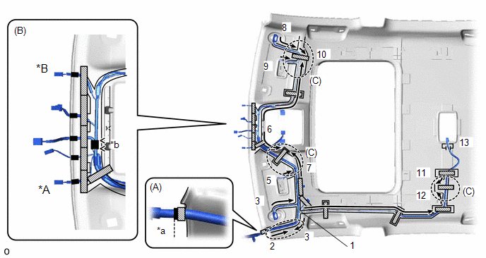
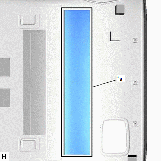
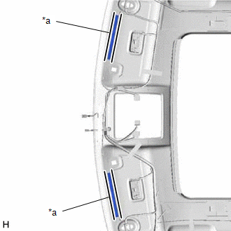
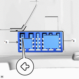
6. INSTALL NO. 1 ROOF WIRE (for Normal Roof)
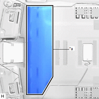
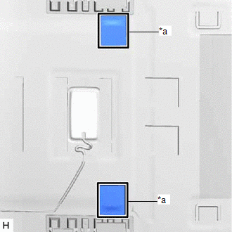
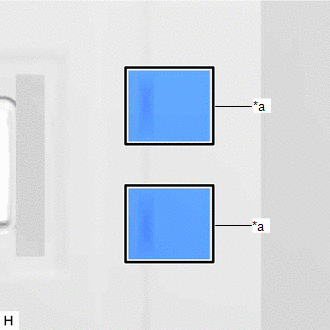
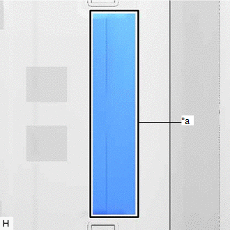
(a) Apply butyl tape as shown in the illustration.
HINT:
Place the tape securely so that it is not misaligned or peeling.
| *a | Butyl Tape | *b | Marking |
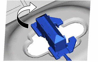
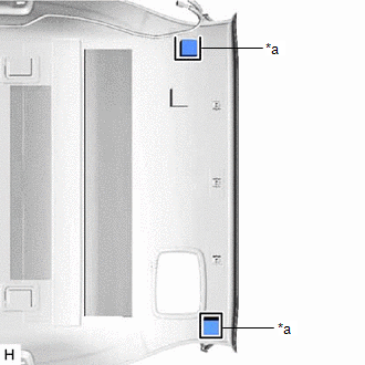
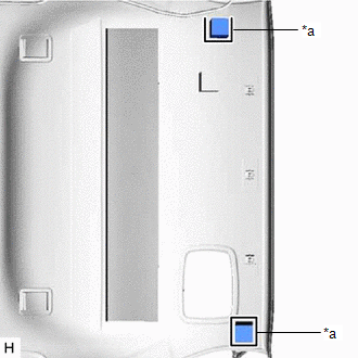
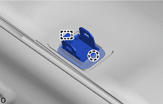
| (b) Turn the visor connectors approximately 90° clockwise to install them to the roof headlining. |
|
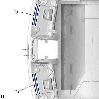
(c) Attach the No. 1 roof wire to the butyl tape in the order and direction indicated by the arrows shown in the illustration and secure the No. 1 roof wire with pieces of fastening tape.
HINT:
- Align the positioning tape of the No. 1 roof wire with the protrusion of the roof headlining and wrap a piece of fastening tape around the No. 1 roof wire and protrusion as shown in the part of the illustration labeled (A).
- Secure the No. 1 roof wire so that the positioning tape does not protrude from the cutout of the roof headlining as shown in the part of the illustration labeled (B).
- Secure the No. 1 roof wire so that the No. 1 roof wire is between the roof headlining V marks as shown in the part of the illustration labeled (B).
- Adjust the slack of the No. 1 roof wire as shown in the parts of the illustration labeled (C).
- Make sure that the No. 1 roof wire is securely attached to the roof headlining along its entire length and not twisted.
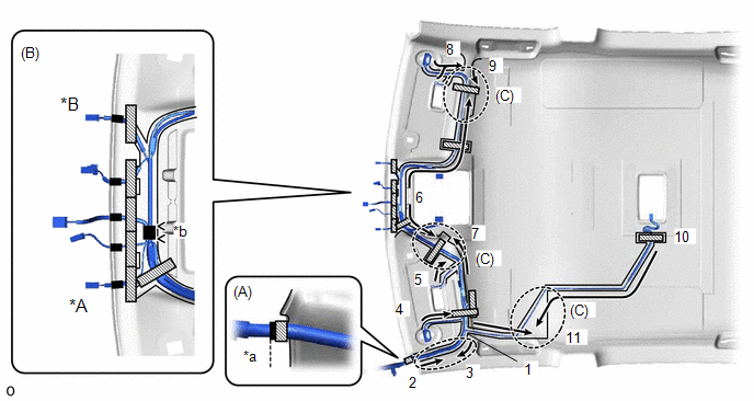
| *A | w/ Humidity Sensor | *B | w/ Rain Sensor |
| *a | Align positioning tape of No. 1 roof wire and protrusion of roof headlining | *b | V Mark |
.png) | Fastening Tape | .png) | Positioning Tape |
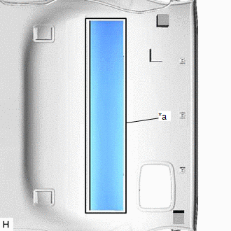
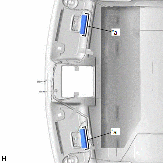
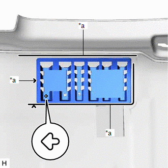
7. INSTALL NO. 1 ROOF WIRE (for Sliding Roof)
(a) Apply butyl tape as shown in the illustration.
HINT:
Place the tape securely so that it is not misaligned or peeling.
| *a | Butyl Tape | *b | Marking |
| (b) Turn the visor connectors approximately 90° clockwise to install them to the roof headlining. |
|
(c) Attach the No. 1 roof wire to the butyl tape in the order and direction indicated by the arrows shown in the illustration and secure the No. 1 roof wire with pieces of fastening tape.
HINT:
- Align the positioning tape of the No. 1 roof wire with the protrusion of the roof headlining and wrap a piece of fastening tape around the No. 1 roof wire and protrusion as shown in the part of the illustration labeled (A).
- Secure the No. 1 roof wire so that the positioning tape does not protrude from the cutout of the roof headlining as shown in the part of the illustration labeled (B).
- Secure the No. 1 roof wire so that the No. 1 roof wire is between the roof headlining V marks as shown in the part of the illustration labeled (B).
- Adjust the slack of the No. 1 roof wire as shown in the parts of the illustration labeled (C).
- Make sure that the No. 1 roof wire is securely attached to the roof headlining along its entire length and not twisted.
| *A | w/ Humidity Sensor | *B | w/ Rain Sensor |
| *a | Align positioning tape of No. 1 roof wire and protrusion of roof headlining | *b | V Mark |
| | Fastening Tape | | Positioning Tape |
8. INSTALL NO. 1 ROOF SILENCER PAD (for Normal Roof)
| (a) Align the No. 1 roof silencer pad with the silencer marking on the roof headlining and install the No. 1 roof silencer pad using double-sided tape or hot-melt glue as shown in the illustration. |
|
9. INSTALL NO. 2 ROOF SILENCER PAD (for Normal Roof)
| (a) Align the No. 2 roof silencer pads with the silencer markings on the roof headlining and install the 2 No. 2 roof silencer pads using double-sided tape or hot-melt glue as shown in the illustration. |
|
10. INSTALL NO. 3 ROOF SILENCER PAD (for Normal Roof)
| (a) Align the No. 3 roof silencer pads with the silencer markings on the roof headlining and install the 2 No. 3 roof silencer pads using double-sided tape or hot-melt glue as shown in the illustration. |
|
11. INSTALL REAR ROOF SILENCER PAD (for Normal Roof)
| (a) Align the rear roof silencer pad with the silencer marking on the roof headlining and install the rear roof silencer pad using double-sided tape or hot-melt glue as shown in the illustration. |
|
12. INSTALL REAR ROOF SILENCER PAD (for Sliding Roof)
| (a) Align the rear roof silencer pad with the silencer marking on the roof headlining and install the rear roof silencer pad using double-sided tape or hot-melt glue as shown in the illustration. |
|
13. INSTALL NO. 4 ROOF SILENCER PAD (for Normal Roof)
| (a) Align the No. 4 roof silencer pad with the silencer marking on the roof headlining and install the No. 4 roof silencer pad using double-sided tape or hot-melt glue as shown in the illustration. |
|
14. INSTALL ROOF HEADLINING PAD (for Normal Roof)
| (a) Align the roof headlining pads with the silencer markings on the roof headlining and install the 2 roof headlining pads using double-sided tape or hot-melt glue as shown in the illustration. |
|
15. INSTALL ROOF HEADLINING PAD (for Sliding Roof)
| (a) Align the roof headlining pads with the silencer markings on the roof headlining and install the 2 roof headlining pads using double-sided tape or hot-melt glue as shown in the illustration. |
|
16. INSTALL FRONT ROOF HEADLINING SIDE PAD (for Normal Roof)
| (a) Align the front roof headlining side pads with the silencer markings on the roof headlining and install the 2 front roof headlining side pads using double-sided tape or hot-melt glue as shown in the illustration. |
|
17. INSTALL ROOF HEADLINING END PAD (for Normal Roof)
| (a) Align the roof headlining end pads with the silencer markings on the roof headlining and install the 2 roof headlining end pads using double-sided tape or hot-melt glue as shown in the illustration. |
|
18. INSTALL ROOF HEADLINING END PAD (for Sliding Roof)
| (a) Align the roof headlining end pads with the silencer markings on the roof headlining and install the 2 roof headlining end pads using double-sided tape or hot-melt glue as shown in the illustration. |
|
19. INSTALL NO. 2 ROOF HEADLINING SUPPORT (for Normal Roof)
| (a) Align the No. 2 roof headlining support with the marking on the roof headlining and install the No. 2 roof headlining support using double-sided tape or hot-melt glue as shown in the illustration. HINT: Make sure to install the support facing the front of the vehicle in the direction of the arrow shown in the illustration. |
|
20. INSTALL ROOF HEADLINING SUPPORT (for Normal Roof)
| (a) Align the roof headlining support with the marking on the roof headlining and install the roof headlining support using double-sided tape or hot-melt glue as shown in the illustration. HINT: Make sure to install the support facing the front of the vehicle in the direction of the arrow shown in the illustration. |
|
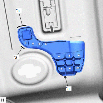
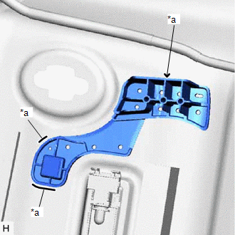
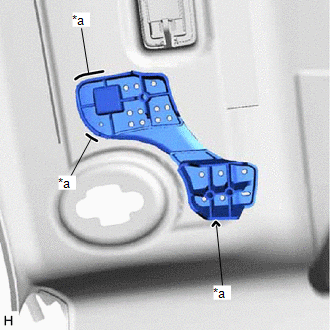
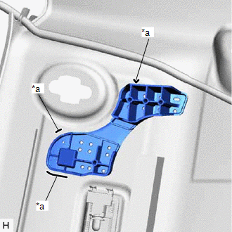
21. INSTALL NO. 1 MICROPHONE CASE
| (a) Attach the guide and claw to install the No. 1 microphone case. |
|
22. INSTALL TELEPHONE MICROPHONE ASSEMBLY
Click here
23. INSTALL VANITY LIGHT ASSEMBLY
HINT:
Use the same procedure for both vanity light assemblies..
| (a) Attach claw A of the vanity light assembly to temporarily install the vanity light assembly to the roof headlining. |
|
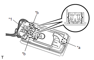
(b) Attach the 2 claws B of the bulb holder to install the vanity light assembly.
24. INSTALL CHILD RESTRAINT SEAT TETHER ANCHOR COVER
| (a) Attach the 2 guides and 2 claws to install the child restraint seat tether anchor cover. |
|
.png)
READ NEXT:
 Installation
INSTALLATION CAUTION / NOTICE / HINT HINT: A bolt without a torque specification is shown in the standard bolt chart. Click here PROCEDURE 1. INSTALL REAR NO. 2 SIDE RAIL SPACER LH (a) Attach the 2
Tonneau Cover Assembly
ComponentsCOMPONENTS ILLUSTRATION *1 NO. 1 TONNEAU COVER HOLDER CAP *2 TONNEAU COVER CAP PLATE *3 REAR TONNEAU COVER CAP *4 CUSHION *5 STRING - - DisassemblyDISASSEM
SEE MORE:
Components
COMPONENTS ILLUSTRATION *1 FRONT SEAT INNER BELT ASSEMBLY LH *2 FRONT SEAT INNER BELT ASSEMBLY RH *3 FRONT SEAT BELT ANCHOR PLATE - - N*m (kgf*cm, ft.*lbf): Specified torque - -
Components
COMPONENTS ILLUSTRATION *1 INNER REAR VIEW MIRROR ASSEMBLY *2 NO. 1 FORWARD RECOGNITION COVER *3 NO. 2 FORWARD RECOGNITION COVER - - N*m (kgf*cm, ft.*lbf): Specified torque - -
