Lexus NX: Installation
INSTALLATION
CAUTION / NOTICE / HINT
HINT:
A bolt without a torque specification is shown in the standard bolt chart.
Click here .gif)
PROCEDURE
1. INSTALL REAR NO. 2 SIDE RAIL SPACER LH
(a) Attach the 2 claws to install the rear No. 2 side rail spacer LH.
(b) Install the 2 bolts.
2. INSTALL REAR NO. 2 SIDE RAIL SPACER RH
HINT:
Use the same procedure described for the LH side.
3. INSTALL REAR SIDE RAIL SPACER LH
(a) Attach the claw to install the rear side rail spacer LH.
(b) Install the 2 bolts.
4. INSTALL REAR SIDE RAIL SPACER RH
HINT:
Use the same procedure described for the LH side.
5. INSTALL CURTAIN SHIELD AIRBAG ASSEMBLY LH
Click here
6. INSTALL CURTAIN SHIELD AIRBAG ASSEMBLY RH
HINT:
Use the same procedure described for the LH side.
7. INSTALL FRONT SHOULDER BELT ANCHOR PLATE SUB-ASSEMBLY LH
| (a) Attach the 6 guides to install the front shoulder belt anchor plate sub-assembly LH. |
|
8. INSTALL FRONT SHOULDER BELT ANCHOR PLATE SUB-ASSEMBLY RH
HINT:
Use the same procedure described for the LH side.
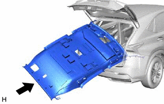
9. INSTALL ROOF HEADLINING ASSEMBLY (for Normal Roof)
| (a) Insert the roof headlining assembly into the cabin from the back door. NOTICE:
|
|
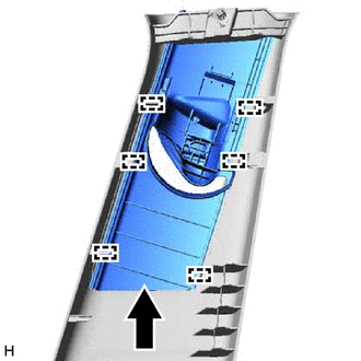
(b) Attach the 3 clips to install the roof headlining assembly.
.png)
| (c) Connect the connector to the rear pillar RH. |
|
.png)
| (d) Connect each connectors. |
|
.png)
| (e) Connect the connectors and attach the clamps to the front pillar LH. |
|
.png)
| (f) Connect the connectors and attach the clamps to the front pillar RH. |
|
.png)
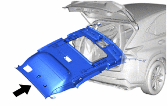
10. INSTALL ROOF HEADLINING ASSEMBLY (for Sliding Roof)
| (a) Insert the roof headlining assembly into the cabin from the back door. NOTICE:
|
|
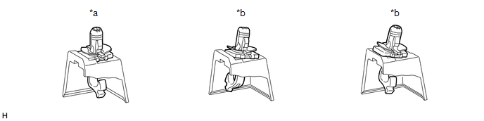
(b) Attach the guide, 3 clips and 8 fasteners to install the roof headlining assembly.
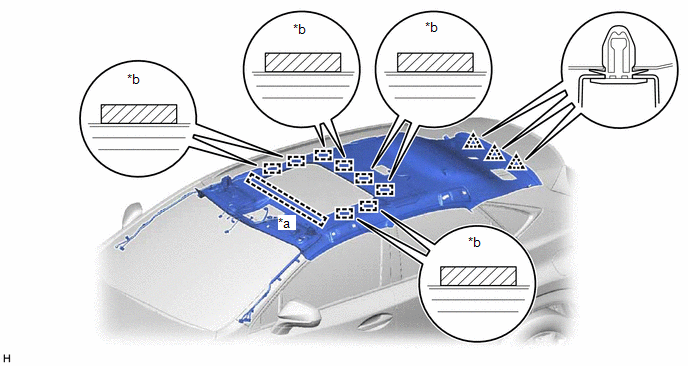
| *a | Guide | *b | Fastener |
| (c) Connect the connector to the rear pillar RH. |
|
| (d) Connect each connector. |
|
.png)
| (e) Connect the drive gear connector. |
|
.png)
| (f) Connect the connectors and attach the clamps to the front pillar LH. |
|
| (g) Connect the connectors and attach the clamps to the front pillar RH. |
|
11. INSTALL PROTECTOR (w/ Humidity Sensor)
Click here
12. INSTALL RAIN SENSOR COVER (w/ Rain Sensor)
Click here
13. INSTALL NO. 1 FORWARD RECOGNITION COVER
Click here
14. INSTALL NO. 2 FORWARD RECOGNITION COVER
Click here
15. INSTALL SEAT BELT ANCHOR COVER
(a) Attach the 2 guides, 2 claws and 3 clips to install the seat belt anchor cover.
16. INSTALL SPOT LIGHT ASSEMBLY (ROOM LIGHT)
Click here
17. INSTALL MAP LIGHT ASSEMBLY
Click here
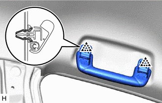
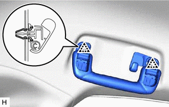
18. INSTALL ASSIST GRIP SUB-ASSEMBLY
HINT:
Use the same procedure for both assist grip sub-assemblies.
| (a) Install the 2 clips and 2 new assist grip covers to the assist grip. |
|
| (b) Attach the 2 clips to install the assist grip sub-assembly. |
|
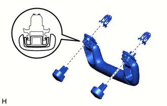
19. INSTALL REAR ASSIST GRIP ASSEMBLY LH
| (a) Install the 2 clips and 2 new assist grip covers to the rear assist grip. |
|
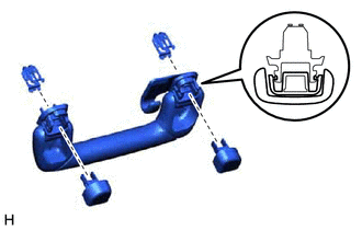
| (b) Attach the 2 clips to install the rear assist grip assembly LH. |
|
20. INSTALL REAR ASSIST GRIP ASSEMBLY RH
HINT:
Use the same procedure described for the LH side.
21. INSTALL VISOR HOLDER
HINT:
Use the same procedure for both visor holders.
| (a) Attach the 2 claws. |
|
(b) Push in the visor holder to install it.
22. INSTALL VISOR ASSEMBLY LH
| (a) Install the visor assembly LH with the 2 screws. |
|
.png)
(b) Connect the visor assembly LH to the visor holder.
23. INSTALL VISOR ASSEMBLY RH
HINT:
Use the same procedure described for the LH side.
24. INSTALL VISOR BRACKET COVER
HINT:
Use the same procedure for both visor bracket covers.
| (a) Attach the 4 claws to install the visor bracket cover. |
|
25. INSTALL INNER ROOF SIDE GARNISH ASSEMBLY LH
(a) Attach the 7 clips to install the inner roof side garnish assembly LH.
26. INSTALL INNER ROOF SIDE GARNISH ASSEMBLY RH
HINT:
Use the same procedure described for the LH side.
27. INSTALL DECK TRIM SIDE PANEL ASSEMBLY LH
(a) Connect the connectors.
(b) Attach the 2 guides, 2 clips and 5 claws to install the deck trim side panel assembly LH.
28. INSTALL DECK TRIM SIDE PANEL ASSEMBLY RH
HINT:
Use the same procedure described for the LH side.
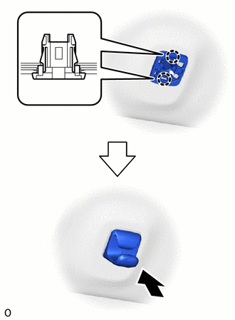
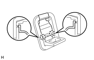
29. INSTALL NO. 1 LUGGAGE COMPARTMENT TRIM HOOK
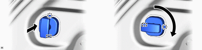
(a) for LH Side:
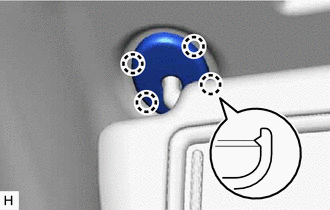
(1) Turn the claw upward as shown in the illustration and insert the No. 1 luggage compartment trim hook.
(2) Turn the No. 1 luggage compartment trim hook in the direction indicated by the arrow shown in the illustration and attach the claw and guide to install the No. 1 luggage compartment trim hook.
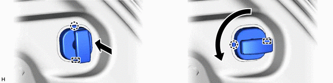
(b) for RH Side:
(1) Turn the claw upward as shown in the illustration and insert the No. 1 luggage compartment trim hook.
(2) Turn the No. 1 luggage compartment trim hook in the direction indicated by the arrow shown in the illustration and attach the claw and guide to install the No. 1 luggage compartment trim hook.
30. INSTALL LUGGAGE HOLD BELT STRIKER ASSEMBLY
HINT:
Use the same procedure for all luggage hold belt striker assemblies.
(a) Install the luggage hold belt striker assembly with the bolt.
31. INSTALL ROPE HOOK ASSEMBLY
HINT:
Use the same procedure for both rope hook assemblies.
| (a) Install the rope hook assembly with the bolt. |
|
.png)
| (b) Attach the 2 claws to close the cover. |
|
32. INSTALL UPPER DECK TRIM SIDE BOARD LH
(a) Attach the guide and 10 claws to install the upper deck trim side board LH.
(b) Install the bolt.
33. INSTALL UPPER DECK TRIM SIDE BOARD RH
HINT:
Use the same procedure described for the LH side.
34. INSTALL NO. 3 BATTERY SERVICE COVER BOARD (for Power Seat)
Click here
35. INSTALL NO. 2 BATTERY SERVICE COVER BOARD (for Power Seat)
Click here
36. INSTALL CENTER PILLAR GARNISH ASSEMBLY LH
(a) Pass the front seat outer belt floor anchor through the center pillar garnish assembly LH.
(b) Attach the clip to install the center pillar garnish assembly LH.
(c) Install the 2 clips.
37. INSTALL CENTER PILLAR GARNISH ASSEMBLY RH
HINT:
Use the same procedure described for the LH side.
38. INSTALL LOWER CENTER PILLAR GARNISH LH
(a) Attach the 4 clips.
(b) While pulling both sides of the lower center garnish LH outward by hand, set the lower center pillar garnish LH in place, and then attach the 2 claws to install the lower center pillar garnish LH.
39. INSTALL LOWER CENTER PILLAR GARNISH RH
HINT:
Use the same procedure described for the LH side.
40. CONNECT FRONT SEAT OUTER BELT ASSEMBLY LH
(a) Connect the front seat outer belt assembly LH with the bolt.
Torque:
42 N·m {428 kgf·cm, 31 ft·lbf}
41. CONNECT FRONT SEAT OUTER BELT ASSEMBLY RH
HINT:
Use the same procedure described for the LH side.
42. INSTALL OUTER LAP BELT ANCHOR COVER
HINT:
Use the same procedure for both outer lap belt anchor covers.
(a) Attach the guide and 2 claws to install the outer lap belt anchor cover.
43. INSTALL FRONT PILLAR GARNISH ASSEMBLY LH
(a) Install the front pillar garnish clips to the front pillar garnish LH.
HINT:
Install the front pillar garnish clips so that it faces as shown in the illustration.
| *a | CORRECT | *b | INCORRECT |
| (b) Attach the 2 guides. |
|
| (c) Attach the 2 front pillar garnish clips to install the front pillar garnish assembly LH. HINT: Make sure that the curtain shield airbag assembly LH is not pinched. |
|
44. INSTALL FRONT PILLAR GARNISH ASSEMBLY RH
HINT:
Use the same procedure described for the LH side.
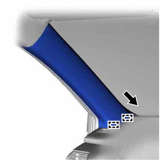
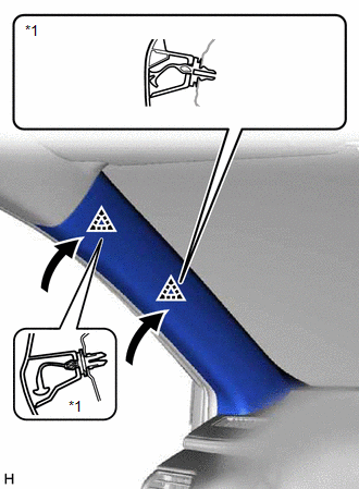
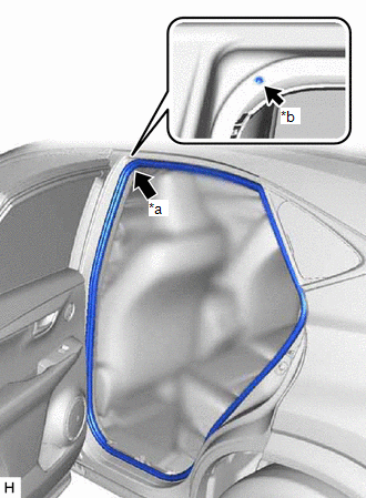
45. INSTALL REAR DOOR OPENING TRIM WEATHERSTRIP LH
| (a) Align the paint mark on the rear door opening trim weatherstrip LH with the mark position on the vehicle and install the rear door opening trim weatherstrip LH as shown in the illustration. |
|
46. INSTALL REAR DOOR OPENING TRIM WEATHERSTRIP RH
HINT:
Use the same procedure described for the LH side.
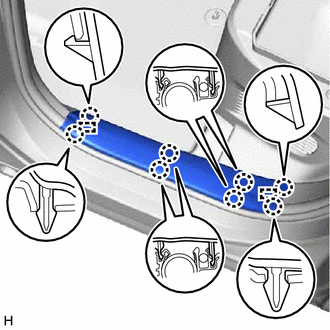
47. INSTALL REAR DOOR SCUFF PLATE LH
| (a) Attach the 2 guides and 8 claws to install the rear door scuff plate LH. |
|
48. INSTALL REAR DOOR SCUFF PLATE RH
HINT:
Use the same procedure described for the LH side.
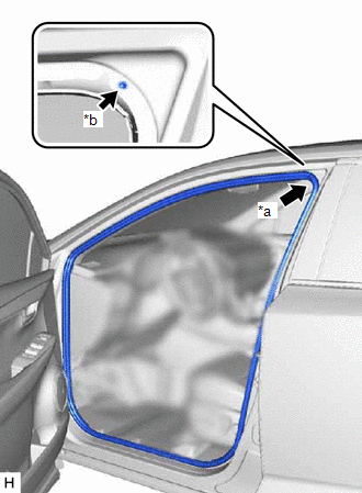
49. INSTALL FRONT DOOR OPENING TRIM WEATHERSTRIP LH
| (a) Align the paint mark on the front door opening trim weatherstrip LH with the mark position on the vehicle and install the front door opening trim weatherstrip LH as shown in the illustration. |
|
50. INSTALL FRONT DOOR OPENING TRIM WEATHERSTRIP RH
HINT:
Use the same procedure described for the LH side.
51. INSTALL COWL SIDE TRIM BOARD LH
(a) Attach the clip to install the cowl side trim board LH.
(b) Install the cap nut.
52. INSTALL COWL SIDE TRIM BOARD RH
HINT:
Use the same procedure described for the LH side.
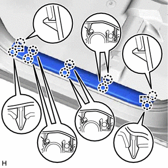
53. INSTALL DOOR SCUFF PLATE ASSEMBLY LH
| (a) Attach the 2 guides and 10 claws to install the door scuff plate assembly LH. |
|
54. INSTALL DOOR SCUFF PLATE ASSEMBLY RH
HINT:
Use the same procedure described for the LH side.
55. INSTALL REAR FLOOR FINISH PLATE
(a) Attach the 4 claws and 4 clips to install the rear floor finish plate.
56. INSTALL NO. 2 TOOL BOX SUB-ASSEMBLY
(a) Attach the 4 guides and 2 clips to install the No. 2 tool box sub-assembly.
(b) Install the screw.
57. INSTALL NO. 1 TOOL BOX SUB-ASSEMBLY
(a) Attach the 5 guides, 2 claws and clip to install the No. 1 tool box sub-assembly.
(b) Install the screw.
58. INSTALL DECK FLOOR BOX RH
(a) Attach the 4 guides to install the deck floor box RH.
(b) Install the 2 clips.
59. INSTALL SPARE TIRE
(a) Install the spare tire.
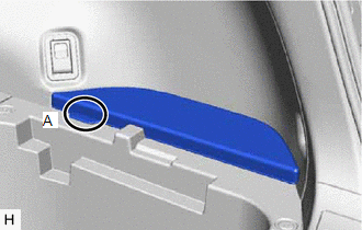
60. INSTALL NO. 2 DECK BOARD SUB-ASSEMBLY
| (a) Install the No. 2 deck board sub-assembly. HINT: Make sure part A shown in illustration faces the vehicle front. |
|
61. INSTALL TONNEAU COVER ASSEMBLY
(a) Install the tonneau cover assembly.
62. INSTALL REAR SEAT ASSEMBLY (for Manual Seat)
Click here
63. INSTALL REAR SEAT ASSEMBLY (for Power Seat)
Click here
64. CONNECT CABLE TO NEGATIVE AUXILIARY BATTERY TERMINAL
65. INITIALIZATION AFTER RECONNECTING AUXILIARY BATTERY TERMINAL
Click here
HINT:
When disconnecting and reconnecting the auxiliary battery, there is an automatic learning function that completes learning when the respective system is used.
Click here
66. CHECK SRS WARNING LIGHT
Click here
67. INSTALL DECK FLOOR BOX LH
(a) Attach the 4 guides to install the deck floor box LH.
(b) Install the 4 clips.
68. INSTALL REAR DECK FLOOR BOX
| (a) Install the rear deck floor box. |
|
.png)
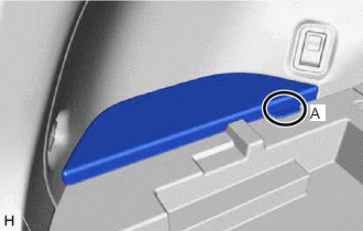
69. INSTALL NO. 3 DECK BOARD SUB-ASSEMBLY
| (a) Install the No. 3 deck board sub-assembly. HINT: Make sure part A shown in illustration faces the vehicle front. |
|
70. INSTALL DECK BOARD ASSEMBLY
| (a) Install the deck board assembly. |
|
.png)
READ NEXT:
 Tonneau Cover Assembly
ComponentsCOMPONENTS ILLUSTRATION *1 NO. 1 TONNEAU COVER HOLDER CAP *2 TONNEAU COVER CAP PLATE *3 REAR TONNEAU COVER CAP *4 CUSHION *5 STRING - - DisassemblyDISASSEM
Precaution
PRECAUTION PRECAUTION FOR VEHICLE WITH AIRBAG (a) Some operations in this section may affect the airbag. Prior to performing the corresponding operations, read the SRS Precaution. Click here
SEE MORE:
Slide Sensor Malfunction (B2650)
DESCRIPTION When the front power seat switch LH does not receive a sensor signal despite forward or backward movement of the seat by power seat motor operation, this DTC is stored. DTC No. Detection Item DTC Detection Condition Trouble Area B2650 Slide Sensor Malfunction The forward
Noise Occurs
PROCEDURE 1. CHECK NOISE CONDITION (a) Check from which direction the noise comes (front left or right, or rear left or right). OK: The location of the noise source can be determined. NG GO TO STEP 3
OK 2. CHECK SPEAKERS (a) Check the installation condi
