Lexus NX: Installation
INSTALLATION
CAUTION / NOTICE / HINT
HINT:
A bolt without a torque specification is shown in the standard bolt chart.
Click here .gif)
PROCEDURE
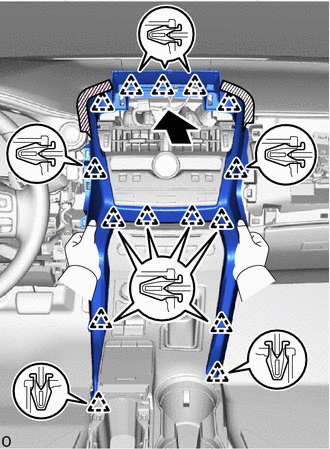
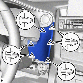
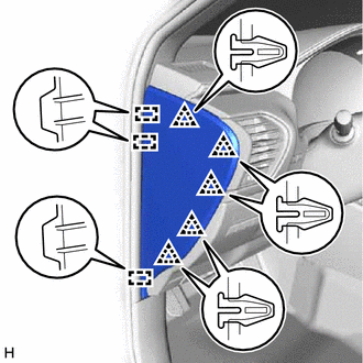
1. INSTALL UPPER INSTRUMENT PANEL SUB-ASSEMBLY
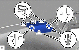
(a) Attach the 5 guides and 7 clips to install the upper instrument panel sub-assembly.
(b) Install the 2 passenger airbag installation bolts <E>.
Torque:
20 N·m {204 kgf·cm, 15 ft·lbf}
(c) Install the 2 bolts <D> and screw <A> or <B>.
(d) Connect the connectors.
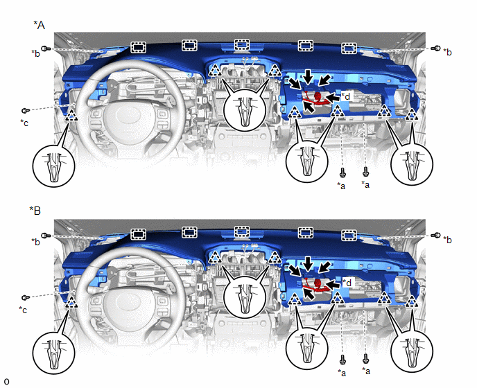
| *A | w/o Headup Display | *B | w/ Headup Display |
| *a | Passenger Airbag Installation Bolt <E> | *b | Bolt <D> |
| *c | Screw <A> or <B> | *d | Passenger Airbag Connector |
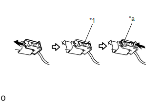
| (e) Connect the passenger airbag connector. NOTICE: When handling the passenger airbag connector, take care not to damage the airbag wire harness. |
|
(f) Check that the lock slider is in the lock position.
2. INSTALL FRONT NO. 3 SPEAKER ASSEMBLY
Click here
3. INSTALL FRONT NO. 2 SPEAKER ASSEMBLY
HINT:
Use the same procedure for both front No. 2 speaker assemblies.
NOTICE:
Do not touch the cone part of the front No. 2 speaker assembly.
| (a) Connect the connector. |
|
.png)
(b) Install the front No. 2 speaker assembly with the 2 screws.
4. INSTALL NO. 1 SPEAKER OPENING COVER ASSEMBLY
| (a) Attach the claw and 4 clips to install the No. 1 speaker opening cover assembly. |
|
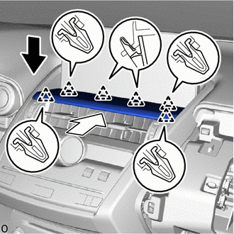
5. INSTALL NO. 1 INSTRUMENT PANEL SPEAKER PANEL SUB-ASSEMBLY
| (a) Attach the 3 guides, 2 claws and 2 clips to install the No. 1 instrument panel speaker panel sub-assembly. |
|
6. INSTALL NO. 2 INSTRUMENT PANEL SPEAKER PANEL SUB-ASSEMBLY
| (a) Attach the 3 guides, 2 claws and 2 clips to install the No. 2 instrument panel speaker panel sub-assembly. |
|
7. INSTALL FRONT PILLAR GARNISH ASSEMBLY LH
Click here
8. INSTALL FRONT PILLAR GARNISH ASSEMBLY RH
Click here
9. CONNECT FRONT DOOR OPENING TRIM WEATHERSTRIP LH
(a) Connect the front door opening trim weatherstrip LH.
10. CONNECT FRONT DOOR OPENING TRIM WEATHERSTRIP RH
(a) Connect the front door opening trim weatherstrip RH.
11. INSTALL GLOVE COMPARTMENT DOOR ASSEMBLY
| (a) Attach the 2 hinges to install the glove compartment door assembly. NOTICE: When installing the glove compartment door assembly, make sure to install horizontally. Installing the glove compartment door assembly from above causes the hinges to become loose. |
|
| (b) While pushing in the sides of the glove compartment door assembly, attach the 2 stoppers. |
|
(c) Attach the claw to connect the glove compartment door stopper sub-assembly.
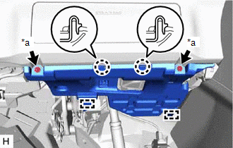
12. INSTALL COMBINATION METER ASSEMBLY
Click here
13. INSTALL INSTRUMENT CLUSTER FINISH PANEL SUB-ASSEMBLY
| (a) Connect the connector. |
|
(b) Attach the 5 clips and 4 claws to install the instrument cluster finish panel sub-assembly.
(c) Install the 2 clips <C>.
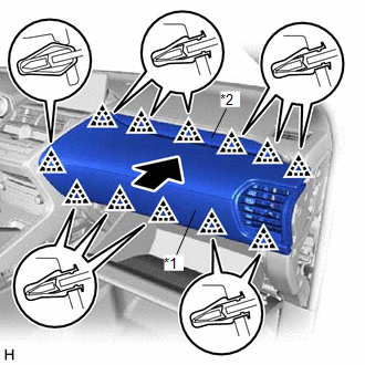
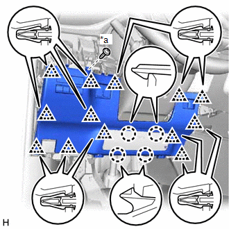
14. INSTALL CENTER INSTRUMENT CLUSTER FINISH PANEL ASSEMBLY
| (a) Attach the 15 clips to install the center instrument cluster finish panel assembly. |
|
15. INSTALL MULTI-DISPLAY ASSEMBLY WITH BRACKET
Click here
16. INSTALL INSTRUMENT PANEL FINISH PLATE
.png) | Install in this Direction (1) |
.png) | Install in this Direction (2) |
(a) Down to the install direction (1) and set the instument panel finish plate.
(b) Push to the install direction (2) and attach the 6 clips to install the instrument panel finish plate.
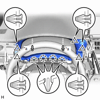
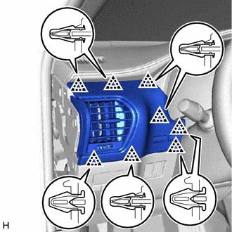
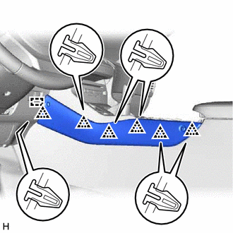
17. INSTALL NO. 2 INSTRUMENT PANEL SAFETY PAD SUB-ASSEMBLY
| (a) Attach the 12 clips to install the No. 2 instrument panel safety pad sub-assembly together with the No. 2 instrument cluster finish panel garnish. |
|
18. INSTALL INSTRUMENT SIDE PANEL RH
| (a) Connect the connector. |
|
(b) Attach the 3 guides and 5 clips to install the instrument side panel RH.
19. INSTALL NO. 1 SWITCH HOLE BASE
| (a) Connect the connector. |
|
(b) Attach the 6 clips to install the No. 1 switch hole base.
20. INSTALL LOWER NO. 1 INSTRUMENT PANEL FINISH PANEL
| (a) Connect the connectors and attach the clamp. |
|
(b) Attach the 13 clips and 4 claws to install the lower No. 1 instrument panel finish panel.
(c) Install the screw <A> or <B>.
21. INSTALL NO. 1 INSTRUMENT PANEL UNDER COVER SUB-ASSEMBLY
| (a) Connect the connector and attach the clamp. |
|
(b) Attach the 2 guides and 2 claws to install the No. 1 instrument panel under cover sub-assembly.
(c) Install the screw <A> or <B>.
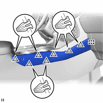
22. INSTALL NO. 1 INSTRUMENT PANEL SAFETY PAD SUB-ASSEMBLY
| (a) Connect the connector. |
|
(b) Attach the 8 clips to install the No. 1 instrument panel safety pad sub-assembly.
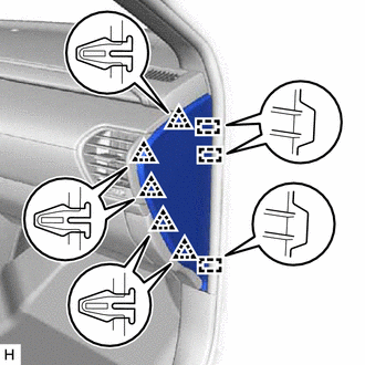
23. INSTALL INSTRUMENT SIDE PANEL LH
| (a) Connect the connector. |
|
(b) Attach the 3 guides and 5 clips to install the instrument side panel LH.
24. INSTALL UPPER NO. 2 CONSOLE PANEL GARNISH
| (a) Attach the guide and 6 clips to install the upper No. 2 console panel garnish. |
|
25. INSTALL UPPER NO. 1 CONSOLE PANEL GARNISH
| (a) Attach the guide and 7 clips to install the upper No. 1 console panel garnish. |
|
26. INSTALL UPPER REAR CONSOLE PANEL
| (a) Attach the 2 clips to install the upper rear console panel. |
|
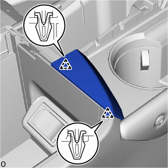
27. INSTALL CONSOLE ARMREST ASSEMBLY
| (a) Attach the 6 clips to install the console armrest assembly. |
|
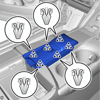
(b) Install the console armrest lid.
28. CONNECT CABLE TO NEGATIVE AUXILIARY BATTERY TERMINAL
29. INITIALIZATION AFTER RECONNECTING AUXILIARY BATTERY TERMINAL
Click here
HINT:
When disconnecting and reconnecting the auxiliary battery, there is an automatic learning function that completes learning when the respective system is used.
Click here
30. ENABLE AUTOAWAY/RETURN FUNCTION
(a) Restore the autoaway/return function setting to the previous condition by changing the customize parameter.
Click here
31. CHECK SRS WARNING LIGHT
Click here
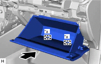
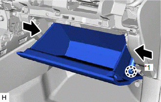
32. INSTALL DECK FLOOR BOX LH
Click here
33. INSTALL REAR DECK FLOOR BOX
Click here
34. INSTALL NO. 3 DECK BOARD SUB-ASSEMBLY
Click here
READ NEXT:
 Components
COMPONENTS ILLUSTRATION *A w/o Power Back Door *B w/ Power Back Door *1 BACK DOOR FINISH COVER LH *2 BACK DOOR FINISH COVER RH *3 BACK DOOR LOCK ASSEMBLY (BACK DOOR COURTESY
SEE MORE:
How To Proceed With Troubleshooting
CAUTION / NOTICE / HINT HINT:
Use these procedures to troubleshoot the LIN communication system.
*: Use the Techstream.
PROCEDURE 1. VEHICLE BROUGHT TO WORKSHOP
NEXT 2. INSPECT AUXILIARY BATTERY VOLTAGE (a) Measure the auxiliary battery voltage with the pow
Installation
INSTALLATION CAUTION / NOTICE / HINT HINT: A bolt without a torque specification is shown in the standard bolt chart. Click here PROCEDURE 1. INSTALL STEREO COMPONENT AMPLIFIER ASSEMBLY 2. INSTALL NO. 2 AMPLIFIER BRACKET (a) Install the No. 2 amplifier bracket with the 2 screws. 3. INSTALL NO. 1 A
