Lexus NX: Drive Start Control System
DESCRIPTION
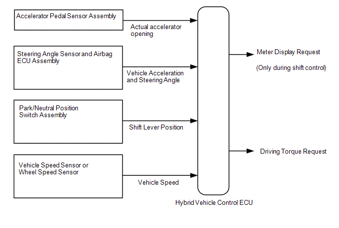
The drive start control is controlled by the hybrid vehicle control ECU.
If the hybrid vehicle control ECU determines that the shift lever and accelerator pedal are operated abnormally, driving torque is restricted and, when necessary, a warning is displayed on the combination meter assembly.
CAUTION / NOTICE / HINT
HINT:
Even if the accelerator pedal position is maintained, the engine output may increase when driving uphill and decrease when driving downhill. This is due to the drive start control controlling the driving torque, and is not a malfunction.
PROCEDURE
| 1. | SYMPTOM CONFIRMATION |
(a) Interview the customer to confirm the problem.
| Hesitation/poor acceleration | .gif) | GO TO STEP 8 |
|
.gif)
| 2. | PAST ACTIVATION CONFIRMATION |
(a) Check if the customer operated the vehicle in a way that would cause the drive start control to operate.
Drive Start Control Activation ConditionsHINT:
Condition 1 (Reverse control)
Activation conditions
- The shift lever is in R.
-
The accelerator pedal is depressed.
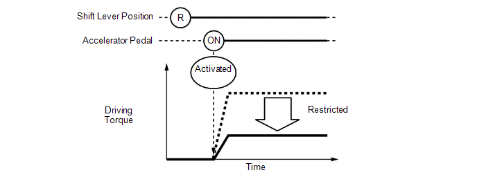
Items Controlled
- Driving torque is restricted.
Deactivation Conditions
- The shift lever is moved to any position other than R.
- The accelerator pedal is released.
Condition 2 (Shift control a)
Activation conditions
- The shift lever is moved from P to any forward position (D or S) or R.
-
The accelerator pedal is open by approximately 1/5 or more.
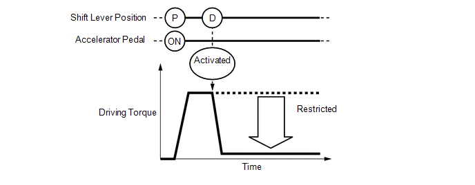
Items Controlled
- Driving torque is restricted.
Deactivation Conditions
- The shift lever is in P or N.
- The accelerator pedal is released.
Condition 3 (Shift control b)
Activation conditions
- The shift lever is moved from R to any forward position (D or S), any forward position (D or S) to R, or N to R.
-
The accelerator pedal is open by approximately 1/5 or more.
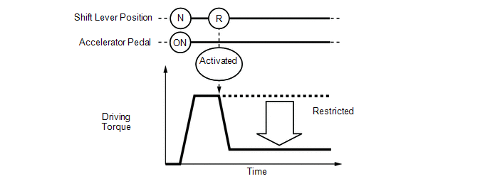
Items Controlled
- Driving torque is restricted.
Deactivation Conditions
- The shift lever is in P or N.
- The accelerator pedal is released.
HINT:
During reverse control or shift control, driving torque is adjusted based on the road gradient and steering angle.
| Not performed | | SYSTEM NORMAL (GO TO PROBLEM SYMPTOM TABLE) |
|
| 3. | CHECK DTC OUTPUT |
(a) Connect the Techstream to the DLC3.
(b) Turn the power switch on (IG).
(c) Enter the following menus: System Select / Health Check.
(d) Check the DTCs.
(e) Turn the power switch off.
| DTC is output | | GO TO DTC CHART |
|
| 4. | READ VALUE USING TECHSTREAM (FR, FL, RR, RL WHEEL SPEED) |
(a) Connect the Techstream to the DLC3.
(b) Turn the power switch on (READY).
(c) Enter the following menus: Chassis / ABS/VSC/TRC / Data List / FR Wheel Speed, FL Wheel Speed, RR Wheel Speed and RL Wheel Speed.
Chassis > ABS/VSC/TRC > Data List| Tester Display |
|---|
| FR Wheel Speed |
| FL Wheel Speed |
| RR Wheel Speed |
| RL Wheel Speed |
| Tester Display | Measurement Item | Range | Normal Condition |
|---|---|---|---|
| FR Wheel Speed | Front speed sensor RH | Min.: 0 km/h (0 mph), Max.: 326 km/h (202 mph) | When driving at constant speed: No large fluctuations |
| FL Wheel Speed | Front speed sensor LH | Min.: 0 km/h (0 mph), Max.: 326 km/h (202 mph) | When driving at constant speed: No large fluctuations |
| RR Wheel Speed | Rear speed sensor RH | Min.: 0 km/h (0 mph), Max.: 326 km/h (202 mph) | When driving at constant speed: No large fluctuations |
| RL Wheel Speed | Rear speed sensor LH | Min.: 0 km/h (0 mph), Max.: 326 km/h (202 mph) | When driving at constant speed: No large fluctuations |
(d) Read the value displayed on the Techstream.
Standard:
| Techstream Display | Condition | Specified Condition |
|---|---|---|
| FR Wheel Speed FL Wheel Speed RR Wheel Speed RL Wheel Speed | Vehicle stopped, engine running | 0 km/h (0 mph) |
| Vehicle being driven at constant speed between 16.1 to 64.4 km/h (10 to 40 mph) | No large fluctuations when driving at a constant speed |
CAUTION:
When performing the confirmation driving pattern, obey all speed limits and traffic laws.
HINT:
Data can be captured relatively easily by using the snapshot function in the Data List. Confirm the data after performing the drive test.
(e) Turn the power switch off.
| NG | | INSPECT FRONT OR REAR SPEED SENSOR |
|
| 5. | READ VALUE USING TECHSTREAM (VEHICLE SPD) |
(a) Connect the Techstream to the DLC3.
(b) Turn the power switch on (IG).
(c) Enter the following menus: Powertrain / Hybrid Control / Data List / Vehicle Spd.
Powertrain > Hybrid Control > Data List| Tester Display |
|---|
| Vehicle Spd |
(d) Read the value of "Vehicle Spd" displayed on the Techstream.
Standard:
| Inspection Condition | Specified Condition |
|---|---|
| Vehicle stopped | 0 km/h (0 mph) |
| Vehicle being driven at a constant speed (16 to 64 km/h (10 to 40 mph)) | No large fluctuations in displayed speed |
CAUTION:
Perform this road test only in an appropriate safe location, in accordance with all local laws.
HINT:
Data can be captured relatively easily by using the snapshot function in the Data List. Confirm the data after performing the drive test.
(e) Turn the power switch off.
| NG | | INSPECT ELECTRONICALLY CONTROLLED BRAKE SYSTEM (HOW TO PROCEED WITH TROUBLESHOOTING) |
|
| 6. | READ VALUE USING TECHSTREAM (DECELERATION SENSOR) |
(a) Connect the Techstream to the DLC3.
(b) Turn the power switch on (READY).
(c) Enter the following menus: Chassis / ABS/VSC/TRC / Data List / Deceleration Sensor and Deceleration Sensor2.
Chassis > ABS/VSC/TRC > Data List| Tester Display |
|---|
| Deceleration Sensor |
| Deceleration Sensor2 |
(d) Read the value displayed on the Techstream.
Standard:
| Techstream Display | Condition | Specified Condition |
|---|---|---|
| Deceleration Sensor Deceleration Sensor2 | During deceleration | Value changes with vehicle speed |
| During acceleration | Value changes with vehicle speed |
CAUTION:
When performing the confirmation driving pattern, obey all speed limits and traffic laws.
HINT:
Data can be captured relatively easily by using the snapshot function in the Data List. Confirm the data after performing the drive test.
(e) Turn the power switch off.
| NG | | INSPECT YAW RATE SENSOR |
|
| 7. | READ VALUE USING TECHSTREAM (STEERING ANGLE SENSOR) |
(a) Connect the Techstream to the DLC3.
(b) Turn the power switch on (READY).
(c) Enter the following menus: Chassis / ABS/VSC/TRC / Data List / Steering Angle Sensor.
Chassis > ABS/VSC/TRC > Data List| Tester Display |
|---|
| Steering Angle Sensor |
| Tester Display | Measurement Item | Range | Normal Condition |
|---|---|---|---|
| Steering Angle Sensor | Steering angle sensor | Min.: -3276.8 degrees, Max.: 3276.7 degrees | Turning left: Increases Turning right: Decreases |
(d) Read the value displayed on the Techstream.
Standard:
| Condition | Specified Condition |
|---|---|
| Steering wheel turned left | Value increases with steering wheel operation |
| Steering wheel turned right | Value decreases with steering wheel operation |
CAUTION:
When performing the confirmation driving pattern, obey all speed limits and traffic laws.
HINT:
Data can be captured relatively easily by using the snapshot function in the Data List. Confirm the data after performing the drive test.
(e) Turn the power switch off.
| OK | | SYSTEM NORMAL (GO TO PROBLEM SYMPTOM TABLE) |
| NG | | INSPECT STEERING ANGLE SENSOR |
| 8. | PAST ACTIVATION CONFIRMATION |
(a) Check if the customer operated the vehicle in a way that would cause the drive start control to operate.
Drive Start Control Activation ConditionsHINT:
Condition 1 (Reverse control)
Activation conditions
- The shift lever is in R.
-
The accelerator pedal is depressed.
Items Controlled
- Driving torque is restricted.
Deactivation Conditions
- The shift lever is moved to any position other than R.
- The accelerator pedal is released.
Condition 2 (Shift control a)
Activation conditions
- The shift lever is moved from P to any forward position (D, S or M) or R.
-
The accelerator pedal is open by approximately 1/5 or more.
Items Controlled
- Driving torque is restricted.
Deactivation Conditions
- The shift lever is in P or N.
- The accelerator pedal is released.
Condition 3 (Shift control b)
Activation conditions
- The shift lever is moved from R to any forward position (D, S or M), any forward position (D, S or M) to R, or N to R.
-
The accelerator pedal is open by approximately 1/5 or more.
Items Controlled
- Driving torque is restricted.
Deactivation Conditions
- The shift lever is in P or N.
- The accelerator pedal is released.
HINT:
During reverse control or shift control, driving torque is adjusted based on the road gradient and steering angle.
| Result | Proceed to |
|---|---|
| Not performed | A |
| Performed | B |
HINT:
If the customer operated the vehicle in a way which caused the drive start control to operate, explain the operation of the system to the customer and that the operation is not a malfunction.
| B | | SYSTEM NORMAL |
|
| 9. | CHECK DTC OUTPUT |
(a) Connect the Techstream to the DLC3.
(b) Turn the power switch on (IG).
(c) Turn the Techstream on.
(d) Enter the following menus: System Select / Health Check.
(e) Check the DTCs.
| Result | Proceed to |
|---|---|
| DTCs are not output | A |
| DTC is output | B |
| B | | GO TO DTC CHART |
|
| 10. | INSPECT PARK/NEUTRAL POSITION SWITCH ASSEMBLY |
(a) Inspect the park/neutral position switch assembly.
Click here .gif)
| Result | Proceed to |
|---|---|
| Normal | A |
| Abnormal | B |
| B | | REPLACE PARK/NEUTRAL POSITION SWITCH ASSEMBLY |
|
| 11. | READ VALUE USING TECHSTREAM (ACCELERATOR PEDAL POSITION SENSOR) |
(a) Connect the Techstream to the DLC3.
(b) Turn the power switch on (IG).
(c) Turn the Techstream on.
(d) Enter the following menus: Powertrain / Hybrid Control / Data List / Accel Pedal Pos.
Powertrain > Hybrid Control > Data List| Tester Display |
|---|
| Accel Pedal Pos #1 |
| Accel Pedal Pos #2 |
| Tester Display | Measurement Item | Range | Normal Condition |
|---|---|---|---|
| Accel Pedal Pos #1 | Accelerator pedal position sensor No. 1 (Sensor voltage is multiplied by 20 and displayed as a percentage) | - | Accelerator pedal depressed: Changes with accelerator pedal pressure |
| Accel Pedal Pos #2 | Accelerator pedal position sensor No. 2 (Sensor voltage is multiplied by 20 and displayed as a percentage) | - | Accelerator pedal depressed: Changes with accelerator pedal pressure |
(e) Read the value displayed on the Techstream.
OK:
| Condition | Specified Condition |
|---|---|
| Accelerator Pedal Released → Depressed | Values smoothly change following accelerator pedal operation |
(f) Turn the power switch off.
| OK | | SYSTEM NORMAL (GO TO PROBLEM SYMPTOM TABLE) |
| NG | | REPLACE ACCELERATOR PEDAL SENSOR ASSEMBLY |
READ NEXT:
 ECU Power Source Circuit
DESCRIPTION If the power switch is on (IG), the hybrid vehicle control ECU applies current to the MREL terminal to turn the IGCT relay on. This supplies power to the +B1 and +B2 terminals. WIRING DIAG
Motor Resolver Circuit
DESCRIPTION The cause of this malfunction may be the motor resolver. Check the motor resolver internal resistance and the connection condition from the inverter to the resolver. Related Parts Check
Motor High-voltage Circuit
DESCRIPTION The cause of the malfunction may be the high-voltage circuit of the motor. Check the motor internal resistance and the connection condition of the high-voltage line between the inverter an
SEE MORE:
Clearance Warning ECU Communication Stop Mode
DESCRIPTION Detection Item Symptom Trouble Area Clearance Warning ECU Communication Stop Mode Any of the following conditions are met:
Communication stop for "Clearance Warning (Intuitive Parking Assist)" is indicated on the "Communication Bus Check" screen of the Techstream.
Click h
Installation
INSTALLATION CAUTION / NOTICE / HINT HINT: A bolt without a torque specification is shown in the standard bolt chart. Click here PROCEDURE 1. INSTALL STEREO COMPONENT AMPLIFIER ASSEMBLY 2. INSTALL NO. 2 AMPLIFIER BRACKET (a) Install the No. 2 amplifier bracket with the 2 screws. 3. INSTALL NO. 1 A
