Lexus NX: Driver Side Door ECU Communication Stop (B2321)
DESCRIPTION
This DTC is stored when LIN communication between the front power window regulator motor assembly LH and main body ECU (multiplex network body ECU) stops for 10 seconds or more.
| DTC No. | Detection Item | DTC Detection Condition | Trouble Area |
|---|---|---|---|
| B2321 | Driver Side Door ECU Communication Stop | No communication between the front power window regulator motor assembly (driver side) and main body ECU for 10 seconds or more. |
|
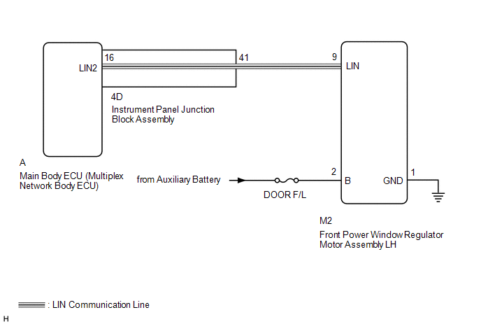
WIRING DIAGRAM
CAUTION / NOTICE / HINT
NOTICE:
-
When using the Techstream with the power switch off to troubleshoot:
Connect the Techstream to the vehicle and turn a courtesy light switch on and off at 1.5 second intervals until communication between the Techstream and vehicle begins.
- Inspect the fuses for circuits related to this system before performing the following inspection procedure.
-
When the front power window regulator motor assembly (driver side) is removed and reinstalled or replaced, the front power window regulator motor assembly (driver side) must be initialized.
Click here
.gif)
- Recognition code registration is necessary when replacing the main body ECU (multiplex network body ECU).
-
If the main body ECU (multiplex network body ECU) is replaced, refer to Registration.
Click here
HINT:
DTC B2325 is output when the communication between all of the following components and main body ECU (multiplex network body ECU) stops.
Click here
PROCEDURE
| 1. | CLEAR DTC |
(a) Clear the DTCs.
Click here
|
.gif)
| 2. | CHECK FOR DTC |
(a) Check for DTCs.
Click here
| DTC B2321 is not output | .gif) | USE SIMULATION METHOD TO CHECK |
|
| 3. | CHECK HARNESS AND CONNECTOR (MAIN BODY ECU [MULTIPLEX NETWORK BODY ECU] - FRONT POWER WINDOW REGULATOR MOTOR ASSEMBLY LH) |
(a) Remove the main body ECU (multiplex network body ECU) from the instrument panel junction block assembly.
Click here
(b) Disconnect the M2 front power window regulator motor assembly LH connector.
(c) Measure the resistance according to the value(s) in the table below.
Standard Resistance:
| Tester Connection | Condition | Specified Condition |
|---|---|---|
| A-16 (LIN2) - M2-9 (LIN) | Always | Below 1 Ω |
| A-16 (LIN2) - Body ground | Always | 10 kΩ or higher |
| NG | | GO TO STEP 7 |
|
| 4. | CHECK HARNESS AND CONNECTOR (FRONT POWER WINDOW REGULATOR MOTOR ASSEMBLY LH - BATTERY AND BODY GROUND) |
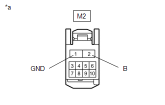
| *a | Front view of wire harness connector (to Front Power Window Regulator Motor Assembly LH) |
(a) Disconnect the front power window regulator motor assembly LH connector.
(b) Measure the resistance according to the value(s) in the table below.
Standard Resistance:
| Tester Connection | Condition | Specified Condition |
|---|---|---|
| M2-1 (GND) - Body ground | Always | Below 1 Ω |
(c) Measure the voltage according to the value(s) in the table below.
Standard Voltage:
| Tester Connection | Switch Condition | Specified Condition |
|---|---|---|
| M2-2 (B) - Body ground | Power switch off | 11 to 14 V |
| NG | | REPAIR OR REPLACE HARNESS OR CONNECTOR |
|
| 5. | REPLACE FRONT POWER WINDOW REGULATOR MOTOR ASSEMBLY LH |
(a) Temporarily replace the front power window regulator motor assembly LH with a new or normally functioning one.
Click here
(b) Clear the DTCs.
Click here
|
| 6. | CHECK FOR DTC |
(a) Check for DTCs.
Click here
| DTC B2321 is not output | | END (FRONT POWER WINDOW REGULATOR MOTOR ASSEMBLY LH IS DEFECTIVE) |
| DTC B2321 is output | | REPLACE MAIN BODY ECU (MULTIPLEX NETWORK BODY ECU) |
| 7. | CHECK HARNESS AND CONNECTOR (INSTRUMENT PANEL JUNCTION BLOCK ASSEMBLY - FRONT POWER WINDOW REGULATOR MOTOR ASSEMBLY LH) |
(a) Remove the main body ECU (multiplex network body ECU) from the instrument panel junction block assembly.
Click here
(b) Disconnect the M2 front power window regulator motor assembly LH connector.
(c) Measure the resistance according to the value(s) in the table below.
Standard Resistance:
| Tester Connection | Condition | Specified Condition |
|---|---|---|
| 4D-41 - M2-9 (LIN) | Always | Below 1 Ω |
| 4D-41 - Body ground | Always | 10 kΩ or higher |
| OK | | REPLACE INSTRUMENT PANEL JUNCTION BLOCK ASSEMBLY |
| NG | | REPAIR OR REPLACE HARNESS OR CONNECTOR |
READ NEXT:
 Front Passenger Side Door ECU Communication Stop (B2322)
DESCRIPTION This DTC is output when LIN communication between the front power window regulator motor assembly RH and main body ECU (multiplex network body ECU) stops for 10 seconds or more. DTC No.
Rear Door RH ECU Communication Stop (B2323)
DESCRIPTION This DTC is output when LIN communication between the rear power window regulator motor assembly RH and main body ECU (multiplex network body ECU) stops for 10 seconds or more. DTC No.
Rear Door LH ECU Communication Stop (B2324)
DESCRIPTION This DTC is output when LIN communication between the rear power window regulator motor assembly LH and main body ECU (multiplex network body ECU) stops for 10 seconds or more. DTC No.
SEE MORE:
Parts Location
PARTS LOCATION ILLUSTRATION *1 VEHICLE SOUND SWITCH *2 STEREO COMPONENT EQUALIZER ASSEMBLY *3 NO. 1 SPEAKER ASSEMBLY WITH BOX *4 HYBRID VEHICLE CONTROL ECU *5 MAIN BODY ECU (MULTIPLEX NETWORK BODY ECU) *6 BRAKE BOOSTER WITH MASTER CYLINDER ASSEMBLY - SKID CONTROL ECU
Parts Location
PARTS LOCATION ILLUSTRATION *1 FUEL INJECTOR ASSEMBLY *2 FUEL PUMP *3 FUEL SENDER GAUGE ASSEMBLY *4 EFI-MAIN RELAY *5 EFI-MAIN NO. 2 RELAY *6 ECM *7 FUEL PUMP CONTROL ECU ASSEMBLY *8 NO. 1 ENGINE ROOM RELAY BLOCK AND JUNCTION BLOCK ASSEMBLY - EFI-MAIN NO. 1 FU
