Lexus NX: Fuel Pump Control Circuit
DESCRIPTION
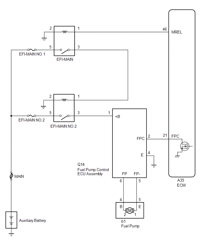
The fuel pump circuit consists of the ECM, fuel pump and fuel pump control ECU assembly (which operates the fuel pump). Based on the engine output, the ECM determines the fuel pump speed. The speed is then converted to a duty signal and sent to the fuel pump control ECU assembly. Based on the signal sent from the ECM, the fuel pump ECU adjusts the fuel pump operation speed.
WIRING DIAGRAM
CAUTION / NOTICE / HINT
NOTICE:
Inspect the fuses for circuits related to this system before performing the following procedure.
PROCEDURE
| 1. | PERFORM ACTIVE TEST USING TECHSTREAM (CONTROL THE FUEL PUMP / SPEED) |
(a) Connect the Techstream to the DLC3.
(b) Turn the power switch on (IG).
(c) Turn the Techstream on.
(d) Enter the following menus: Powertrain / Engine and ECT / Active Test / Control the Fuel Pump / Speed.
Powertrain > Engine and ECT > Active Test| Tester Display |
|---|
| Control the Fuel Pump / Speed |
(e) Check whether the fuel pump operating sounds occurs when performing the Active Test on the Techstream.
| Result | Proceed to |
|---|---|
| Fuel pump operating sound occurs | A |
| Fuel pump operating sound does not occur | B |
| B | .gif) | GO TO STEP 6 |
|
.gif)
| 2. | PERFORM ACTIVE TEST USING TECHSTREAM (CONTROL THE FUEL PUMP DUTY) |
(a) Remove the fuel suction tube assembly.
Click here .gif)
(b) Clean the fuel suction tube assembly to completely remove any remaining fuel.
(c) Remove the fuel pump.
Click here
(d) Connect the fuel pump and fuel suction tube assembly connectors.
NOTICE:
Confirm that no fuel remains inside or on the outside of the fuel pump.
(e) Connect the Techstream to the DLC3.
(f) Turn the power switch on (IG).
(g) Turn the Techstream on.
(h) Enter the following menus: Powertrain / Engine and ECT / Active Test / Control the Fuel Pump Duty.
Powertrain > Engine and ECT > Active Test| Tester Display |
|---|
| Control the Fuel Pump Duty |
| (i) Operate the fuel pump using the Active Test measure the voltage according to the value(s) in the table below. Standard Voltage:
|
|
(j) Enter the following menus: Powertrain / Engine and ECT / Active Test / Control the Fuel Pump / Speed.
Powertrain > Engine and ECT > Active Test| Tester Display |
|---|
| Control the Fuel Pump / Speed |
(k) Operate the fuel pump using the Active Test function and measure the voltage according to the value(s) in the table below.
Standard Voltage:
| Tester Connection | Techstream Operation | Specified Condition |
|---|---|---|
| 1 - 2 | ON (Fuel pump control duty: 90%) | 9.0 to 14.0 V |
HINT:
- Be sure to measure the voltage with all the connectors connected.
- Before performing this inspection, check that the auxiliary battery voltage is between 11 and 14 V (not depleted).
| NG | | GO TO STEP 7 |
|
| 3. | INSPECT FUEL PUMP |
(a) Inspect the fuel pump.
Click here
| OK | | END |
|
| 4. | REPLACE FUEL PUMP |
(a) Replace the fuel pump.
Click here
HINT:
Perform "Inspection After Repair" after replacing the fuel pump.
Click here
|
| 5. | CONFIRM WHETHER MALFUNCTION HAS BEEN SUCCESSFULLY REPAIRED |
(a) Check the fuel pump operation.
OK:
Malfunction has been repaired successfully.
| OK | | END |
| NG | | PROCEED TO NEXT SUSPECTED AREA SHOWN IN PROBLEM SYMPTOMS TABLE |
| 6. | CHECK TERMINAL VOLTAGE (POWER SOURCE OF FUEL PUMP CONTROL ECU ASSEMBLY) |
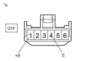
| (a) Disconnect the fuel pump control ECU Assembly connector. |
|
(b) Turn the power switch on (IG).
(c) Measure the voltage according to the value(s) in the table below.
Standard Voltage:
| Tester Connection | Condition | Specified Condition |
|---|---|---|
| Q14-1 (+B) - Q14-4 (E) | Power switch on (IG) | 11 to 14 V |
| NG | | GO TO STEP 11 |
|
| 7. | INSPECT FUEL PUMP |
(a) Inspect the fuel pump.
Click here
HINT:
Perform "Inspection After Repair" after replacing the fuel pump.
Click here
| NG | | REPLACE FUEL PUMP |
|
| 8. | CHECK HARNESS AND CONNECTOR (FUEL PUMP - FUEL PUMP CONTROL ECU ASSEMBLY) |
(a) Disconnect the fuel pump control ECU assembly connector.
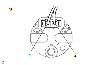
(b) Disconnect the fuel pump connector.
(c) Measure the resistance according to the value(s) in the table below.
Standard Resistance:
| Tester Connection | Condition | Specified Condition |
|---|---|---|
| b1-4 (B) - Q14-6 (FP) | Always | Below 1 Ω |
| b1-5 (E) - Q14-5 (FP-) | Always | Below 1 Ω |
| b1-4 (B) or Q14-6 (FP) - Body ground | Always | 10 kΩ or higher |
| b1-5 (E) or Q14-5 (FP-) - Body ground | Always | 10 kΩ or higher |
| NG | | REPAIR OR REPLACE HARNESS OR CONNECTOR |
|
| 9. | CHECK HARNESS AND CONNECTOR (FUEL PUMP CONTROL ECU ASSEMBLY - ECM) |
(a) Disconnect the fuel pump control ECU assembly connector.
(b) Disconnect the ECM connector.
(c) Measure the resistance according to the value(s) in the table below.
Standard Resistance:
| Tester Connection | Condition | Specified Condition |
|---|---|---|
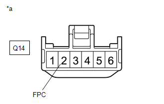
| Q14-2 (FPC) - A35-21 (FPC) | Always | Below 1 Ω |
| Q14-2 (FPC) or A35-21 (FPC) - Body ground | Always | 10 kΩ or higher |
| NG | | REPAIR OR REPLACE HARNESS OR CONNECTOR |
|
| 10. | INSPECT ECM (FPC TERMINAL) |
| (a) Disconnect the fuel pump control ECU assembly connector. |
|
(b) Connect the Techstream to the DLC3.
(c) Turn the power switch on (IG).
(d) Turn the Techstream on.
(e) Enter the following menus: Powertrain / Engine and ECT / Active Test / Control the Fuel Pump / Speed.
Powertrain > Engine and ECT > Active Test| Tester Display |
|---|
| Control the Fuel Pump / Speed |
(f) Operate the fuel pump control ECU assembly using the Active Test function and measure the resistance according to the value(s) in the table below.
Standard Resistance:
| Tester Connection | Techstream Operation | Specified Condition |
| Q14-2 (FPC) - Body ground | Before Active Test → During Active Test | Before Active Test: Resistance is stable → During Active Test: Resistance fluctuates* |
HINT:
*: Using the Active Test, duty control of the transistors in the ECM will be performed. Due to the duty control, resistance of the FPC terminal will be unstable during the Active Test. If the resistance is stable before the Active Test and fluctuates while performing the Active Test, it can be determined that the transistor is operating. If the transistor does not operate during the Active Test, the ECM may be malfunctioning.
| OK | | REPLACE FUEL PUMP CONTROL ECU ASSEMBLY |
| NG | | REPLACE ECM |
| 11. | CHECK HARNESS AND CONNECTOR (FUEL PUMP CONTROL ECU ASSEMBLY - BODY GROUND) |
(a) Disconnect the fuel pump control ECU assembly connector.
(b) Measure the resistance according to the value(s) in the table below.
Standard Resistance:
| Tester Connection | Condition | Specified Condition |
|---|---|---|
| Q14-4 (E) - Body ground | Always | Below 1 Ω |
| NG | | REPAIR OR REPLACE HARNESS OR CONNECTOR |
|
| 12. | INSPECT EFI-MAIN NO. 2 RELAY |
(a) Inspect the EFI-MAIN NO. 2 relay.
Click here
| NG | | REPLACE EFI-MAIN NO. 2 RELAY |
|
| 13. | CHECK HARNESS AND CONNECTOR (POWER SOURCE VOLTAGE OF EFI-MAIN NO. 2 RELAY) |
.png)
| *1 | No. 1 Engine Room Relay Block and Junction Block Assembly |
| *2 | EFI-MAIN NO. 2 Relay |
(a) Remove the EFI-MAIN NO. 2 relay from the No. 1 engine room relay block and junction block assembly.
(b) Measure the voltage according to the value(s) in the table below.
Standard Voltage:
| Tester Connection | Condition | Specified Condition |
|---|---|---|
| 5 (EFI-MAIN NO. 2 relay) - Body ground | Always | 11 to 14 V |
| NG | | REPAIR OR REPLACE HARNESS OR CONNECTOR |
|
| 14. | CHECK HARNESS AND CONNECTOR (NO. 1 ENGINE ROOM RELAY BLOCK - FUEL PUMP CONTROL ECU ASSEMBLY) |
(a) Remove the EFI-MAIN relay from the No. 1 engine room relay block and junction block assembly.
(b) Remove the EFI-MAIN NO. 2 relay from the No. 1 engine room relay block and junction block assembly.
(c) Disconnect the fuel pump control ECU assembly connector.
(d) Measure the resistance according to the value(s) in the table below.
Standard Resistance:
| Tester Connection | Condition | Specified Condition |
|---|---|---|
| 1 (EFI-MAIN NO. 2 relay) - 3 (EFI-MAIN relay) | Always | Below 1 Ω |
| 2 (EFI-MAIN NO. 2 relay) - Body ground | Always | Below 1 Ω |
| 3 (EFI-MAIN NO. 2 relay) - Q14-1 (+B) | Always | Below 1 Ω |
| 1 (EFI-MAIN NO. 2 relay) or 3 (EFI-MAIN relay) - Body ground | Always | 10 kΩ or higher |
| 3 (EFI-MAIN NO. 2 relay) or Q14-1 (+B) - Body ground | Always | 10 kΩ or higher |
| OK | | GO TO ECM POWER SOURCE CIRCUIT |
| NG | | REPAIR OR REPLACE HARNESS OR CONNECTOR |
READ NEXT:
 Fuel Injector Circuit
DESCRIPTION The fuel injector assemblies are located on the intake port. They inject fuel into the cylinders based on the signals from the ECM. WIRING DIAGRAM CAUTION / NOTICE / HINT NOTICE: Inspect
MIL Circuit
DESCRIPTION The Malfunction Indicator Lamp (MIL) is used to indicate vehicle malfunctions detected by the ECM. The MIL operation can be checked visually. When the power switch is turned on (IG), the M
Rough Idling
DESCRIPTION Problem Symptom Suspected Area Trouble Area
Engine speed fluctuation due to abnormal combustion
Idle speed too low or high
Strong engine vibration due to above symptoms
SEE MORE:
Terminals Of Ecu
TERMINALS OF ECU CHECK ABSORBER CONTROL ECU *a Component with harness connected (Absorber Control ECU) - - HINT:
Inspect the connectors from the back side while the connectors are connected.
Check the operation of a particular valve by listening for operating sounds or by using the
Vanity Light Bulb
ReplacementREPLACEMENT CAUTION / NOTICE / HINT HINT:
Use the same procedure for the RH and LH sides.
The procedure listed below is for the LH side.
PROCEDURE 1. DISCONNECT VANITY LIGHT ASSEMBLY (a) Using a screwdriver, detach the claw and disconnect the vanity light assembly. HINT: Tape
