Lexus NX: VC Output Circuit
DESCRIPTION
The ECM constantly generates 5 V power source voltage from the auxiliary battery voltages supplied to the +B (BATT) terminal to operate the microprocessor. The ECM also provides this power source voltage to the sensors through the VC output circuit.
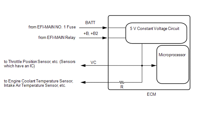
When the VC circuit has a short circuit, the microprocessor in the ECM and sensors that are supplied power through the VC circuit are deactivated because power is not supplied from the VC circuit. When the system is in this condition, it will not start.
WIRING DIAGRAM
-
For the circuit diagram of the ECM power source refer to the ECM power source circuit.
Click here
.gif)
-
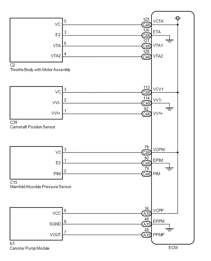
VC Output Circuit
PROCEDURE
| 1. | CHECK CONNECTION BETWEEN TECHSTREAM AND ECM |
(a) Connect the Techstream to the DLC3.
(b) Turn the power switch on (IG).
(c) Turn the Techstream on.
(d) Check the communication between the Techstream and ECM.
HINT:
It can be checked using the "Engine" item of the Data List.
| Result | Proceed to |
|---|---|
| Communication is not possible | A |
| Communication is possible | B |
| B | .gif) | PROCEED TO NEXT SUSPECTED AREA SHOWN IN PROBLEM SYMPTOMS TABLE |
|
.gif)
| 2. | CHECK EFI NO. 1 FUSE VOLTAGE |
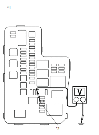
| *1 | No. 1 Engine Room Relay Block and No. 1 Junction Block Assembly |
| *2 | EFI NO. 1 Fuse |
(a) Turn the power switch on (IG).
(b) Measure the voltage according to the value(s) in the table below.
Standard Voltage:
| Tester Connection | Condition | Specified Condition |
|---|---|---|
| 1 (EFI NO. 1 fuse) - Body ground | Power switch on (IG) | 11 to 14 V |
HINT:
- Check the fuse with it installed to the No. 1 engine room relay block and No. 1 junction block assembly.
- If the result is not as specified, since current is not flowing to the +B and +B2 terminals of the ECM, the system may not be started.
| NG | | GO TO ECM POWER SOURCE CIRCUIT |
|
| 3. | CHECK CONNECTION BETWEEN TECHSTREAM AND ECM (THROTTLE POSITION SENSOR) |
(a) Disconnect the throttle body with motor assembly connector.
(b) Turn the power switch on (IG).
(c) Turn the Techstream on.
(d) Check the communication between the Techstream and ECM.
HINT:
It can be checked using the "Engine" item of the Data List.
| Result | Proceed to |
|---|---|
| Communication is not possible | A |
| Communication is possible | B |
HINT:
Perform "Inspection After Repair" after replacing the throttle body with motor assembly.
Click here
| B | | REPLACE THROTTLE BODY WITH MOTOR ASSEMBLY |
|
| 4. | CHECK CONNECTION BETWEEN TECHSTREAM AND ECM (CAMSHAFT POSITION SENSOR) |
(a) Disconnect the camshaft position sensor connector.
(b) Turn the power switch on (IG).
(c) Turn the Techstream on.
(d) Check the communication between the Techstream and ECM.
HINT:
It can be checked using the "Engine" item of the Data List.
| Result | Proceed to |
|---|---|
| Communication is not possible | A |
| Communication is possible | B |
| B | | REPLACE CAMSHAFT POSITION SENSOR |
|
| 5. | CHECK CONNECTION BETWEEN TECHSTREAM AND ECM (MANIFOLD ABSOLUTE PRESSURE SENSOR) |
(a) Disconnect the manifold absolute pressure sensor connector.
(b) Turn the power switch on (IG).
(c) Turn the Techstream on.
(d) Check the communication between the Techstream and ECM.
HINT:
It can be checked using the "Engine" item of the Data List.
| Result | Proceed to |
|---|---|
| Communication is not possible | A |
| Communication is possible | B |
| B | | REPLACE MANIFOLD ABSOLUTE PRESSURE SENSOR |
|
| 6. | CHECK CONNECTION BETWEEN TECHSTREAM AND ECM (CANISTER PUMP MODULE) |
(a) Disconnect the canister pump module connector.
(b) Turn the power switch on (IG).
(c) Turn the Techstream on.
(d) Check the communication between the Techstream and ECM.
HINT:
It can be checked using the "Engine" item of the Data List.
| Result | Proceed to |
|---|---|
| Communication is not possible | A |
| Communication is possible | B |
| B | | REPLACE CANISTER PUMP MODULE |
|
| 7. | CHECK HARNESS AND CONNECTOR (VC CIRCUIT) |
(a) Disconnect the throttle body with motor assembly connector.
(b) Disconnect the camshaft position sensor connector.
(c) Disconnect the manifold absolute pressure sensor connector.
(d) Disconnect the canister pump module connector.
(e) Disconnect the ECM connector.
(f) Measure the resistance according to the value(s) in the table below.
Standard Resistance:
| Tester Connection | Condition | Specified Condition |
|---|---|---|
| C2-5 (VC) or C48-125 (VCTA) - Body ground | Always | 10 kΩ or higher |
| C39-3 (VC) or C48-113 (VCV1) - Body ground | Always | 10 kΩ or higher |
| C15-3 (VC) or C48-78 (VCPM) - Body ground | Always | 10 kΩ or higher |
| b3-6 (VCC) or A35-34 (VCPP) - Body ground | Always | 10 kΩ or higher |
(g) Remove the EFI NO. 1 fuse and EFI-MAIN NO. 2 relay from the No. 1 engine room relay block and No. 1 junction block assembly.
HINT:
Remove the EFI NO. 1 fuse and EFI-MAIN NO. 2 relay connected between the checked terminals as the coil inside the relay influences the measurement value.
(h) Measure the resistance according to the value(s) in the table below.
Standard Resistance:
| Tester Connection | Condition | Specified Condition |
|---|---|---|
| A24-9 (+B) - 1 (EFI NO. 1 fuse) | Always | Below 1 Ω |
| A24-35 (+B2) - 1 (EFI NO. 1 fuse) | Always | Below 1 Ω |
| A24-9 (+B) - Body ground and other terminals | Always | 10 kΩ or higher |
| A24-35 (+B2) - Body ground and other terminals | Always | 10 kΩ or higher |
| OK | | REPLACE ECM |
| NG | | REPAIR OR REPLACE HARNESS OR CONNECTOR |
READ NEXT:
 Fuel Pump Control Circuit
DESCRIPTION The fuel pump circuit consists of the ECM, fuel pump and fuel pump control ECU assembly (which operates the fuel pump). Based on the engine output, the ECM determines the fuel pump speed.
Fuel Injector Circuit
DESCRIPTION The fuel injector assemblies are located on the intake port. They inject fuel into the cylinders based on the signals from the ECM. WIRING DIAGRAM CAUTION / NOTICE / HINT NOTICE: Inspect
MIL Circuit
DESCRIPTION The Malfunction Indicator Lamp (MIL) is used to indicate vehicle malfunctions detected by the ECM. The MIL operation can be checked visually. When the power switch is turned on (IG), the M
SEE MORE:
ICS Detection Area Adjustment Incomplete (C1AF0)
DESCRIPTION When ICS detection area adjustment is incomplete, the clearance warning ECU assembly stores DTC C1AF0. DTC No. Detection Item DTC Detection Condition Trouble Area C1AF0 ICS Detection Area Adjustment Incomplete ICS detection area adjustment incomplete
Intelligent cle
Components
COMPONENTS ILLUSTRATION *1 NO. 1 ENGINE UNDER COVER ASSEMBLY - - ILLUSTRATION *1 INVERTER BRACKET ASSEMBLY *2 INVERTER WATER PUMP WITH MOTOR ASSEMBLY *3 NO. 5 INVERTER COOLING HOSE *4 TRANSMISSION CONTROL CABLE ASSEMBLY *5 TRANSMISSION OIL COOLER ASSEMBLY *6
