Lexus NX: Sliding Roof does not Move by Operating Sliding Roof Control Switch
DESCRIPTION
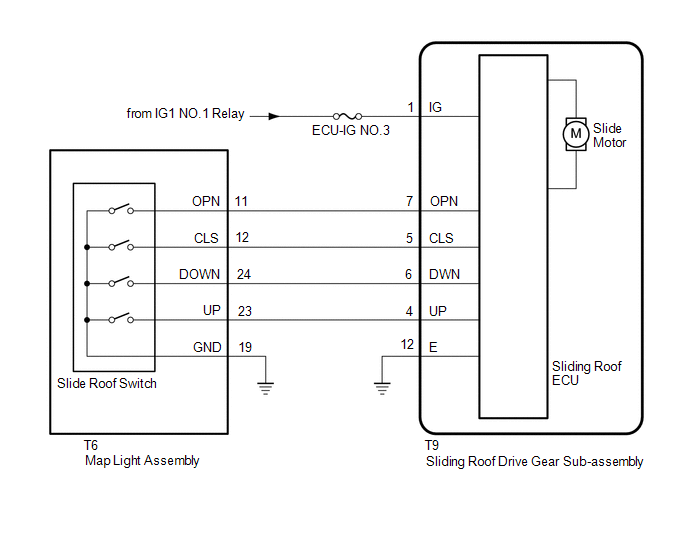
The sliding roof drive gear sub-assembly (sliding roof ECU) receives each signal when the map light assembly (slide roof switch) is operated and drives its built-in motor.
WIRING DIAGRAM
CAUTION / NOTICE / HINT
NOTICE:
- Inspect the fuses for circuits related to this system before performing the following procedure.
-
If the sliding roof drive gear sub-assembly (sliding roof ECU) is replaced, the sliding roof drive gear sub-assembly (sliding roof ECU) must be initialized.
Click here
.gif)
-
The sliding roof system uses the LIN communication system. First, confirm that there are no malfunctions in the LIN communication system. Refer to How to Proceed with Troubleshooting.
Click here
-
If a sliding roof ECU (sliding roof drive gear sub-assembly) DTC is output, first perform troubleshooting for the sliding roof ECU (sliding roof drive gear sub-assembly) DTC.
Click here
PROCEDURE
| 1. | PERFORM ACTIVE TEST USING TECHSTREAM (Slide Roof) |
(a) Connect the Techstream to the DLC3.
(b) Turn the power switch on (IG).
(c) Turn the Techstream on.
(d) Enter the following menus: Body Electrical / Slide Roof / Active Test.
(e) Perform the Active Test according to the display on the Techstream.
Body Electrical > Sliding Roof > Active Test| Tester Display | Measurement Item | Control Range | Diagnostic Note |
|---|---|---|---|
| Slide Roof | Operate sliding roof motor | OFF / Opn/Dwn / Clos/Up | - |
| Tester Display |
|---|
| Slide Roof |
OK:
Slide roof is operated using Techstream.
| OK | .gif) | REPLACE SLIDING ROOF DRIVE GEAR SUB-ASSEMBLY |
|
.gif)
| 2. | READ VALUE USING TECHSTREAM (Open Switch, Close Switch, Up Switch, Down Switch) |
(a) Connect the Techstream to the DLC3.
(b) Turn the power switch on (IG).
(c) Turn the Techstream on.
(d) Enter the following menus: Body Electrical / Sliding Roof / Data List.
(e) Read the Data List according to the display on the Techstream.
Body Electrical > Sliding Roof > Data List| Tester Display | Measurement Item | Range | Normal Condition | Diagnostic Note |
|---|---|---|---|---|
| Open Switch | OPEN switch signal | OFF or ON | OFF: OPEN switch not pressed ON: OPEN switch pressed | - |
| Close Switch | CLOSE switch signal | OFF or ON | OFF: CLOSE switch not pressed ON: CLOSE switch pressed | - |
| Up Switch | UP switch signal | OFF or ON | OFF: UP switch not pressed ON: UP switch pressed | - |
| Down Switch | DOWN switch signal | OFF or ON | OFF: DOWN switch not pressed ON: DOWN switch pressed | - |
| Tester Display |
|---|
| Open Switch |
| Close Switch |
| Up Switch |
| Down Switch |
OK:
The Techstream display changes according to switch operation as shown in the table.
| OK | | REPLACE SLIDING ROOF DRIVE GEAR SUB-ASSEMBLY |
|
| 3. | INSPECT MAP LIGHT SWITCH |
(a) Remove the map light assembly (slide roof switch).
Click here
(b) Inspect the map light assembly (slide roof switch).
Click here
| NG | | REPLACE MAP LIGHT ASSEMBLY |
|
| 4. | CHECK HARNESS AND CONNECTOR (SLIDING ROOF DRIVE GEAR SUB-ASSEMBLY - BATTERY AND BODY GROUND) |
| (a) Disconnect the sliding roof drive gear sub-assembly connector. |
|
(b) Measure the voltage according to the value(s) in the table below.
Standard Voltage:
| Tester Connection | Switch Condition | Specified Condition |
|---|---|---|
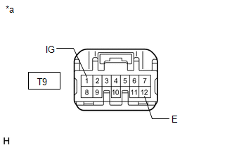
| T9-1 (IG) - Body ground | Power switch on (IG) | 11 to 14 V |
| T9-1 (IG) - Body ground | Power switch off | Below 1 V |
(c) Measure the resistance according to the value(s) in the table below.
Standard Resistance:
| Tester Connection | Condition | Specified Condition |
|---|---|---|
| T9-12 (E) - Body ground | Always | Below 1 Ω |
| NG | | REPAIR OR REPLACE HARNESS OR CONNECTOR |
|
| 5. | CHECK HARNESS AND CONNECTOR (SLIDING ROOF DRIVE GEAR SUB-ASSEMBLY - MAP LIGHT ASSEMBLY AND BODY GROUND) |
(a) Disconnect the T9 sliding roof drive gear sub-assembly connector.
(b) Disconnect the T6 map light assembly connector.
(c) Measure the resistance according to the value(s) in the table below.
Standard Resistance:
| Tester Connection | Condition | Specified Condition |
|---|---|---|
| T9-4 (UP) - T6-23 (UP) | Always | Below 1 Ω |
| T9-4 (UP) or T6-23 (UP) - Body ground | Always | 10 kΩ or higher |
| T9-5 (CLS) - T6-12 (CLS) | Always | Below 1 Ω |
| T9-5 (CLS) or T6-12 (CLS) - Body ground | Always | 10 kΩ or higher |
| T9-6 (DWN) - T6-24 (DOWN) | Always | Below 1 Ω |
| T9-6 (DWN) or T6-24 (DOWN) - Body ground | Always | 10 kΩ or higher |
| T9-7 (OPN) - T6-11 (OPN) | Always | Below 1 Ω |
| T9-7 (OPN) or T6-11 (OPN) - Body ground | Always | 10 kΩ or higher |
| T9-12 (E) - Body ground | Always | Below 1 Ω |
| T6-19 (GND) - Body ground | Always | Below 1 Ω |
| OK | | REPLACE SLIDING ROOF DRIVE GEAR SUB-ASSEMBLY |
| NG | | REPAIR OR REPLACE HARNESS OR CONNECTOR |
READ NEXT:
 Components
COMPONENTS ILLUSTRATION *A w/o Power Back Door *B w/ Power Back Door *1 BACK DOOR CENTER GARNISH *2 BACK DOOR FINISH COVER LH *3 BACK DOOR FINISH COVER RH *4 BACK DOOR SI
SEE MORE:
Precaution
PRECAUTION NOTICE: When disassembling the headlight assembly, use static electricity countermeasures SST (desktop antistatic mat set) and observe all precautions to prevent damage to the system by electrostatic discharge (ESD). STATIC ELECTRICITY COUNTERMEASURES SST SST:Desktop antistatic mat set (0
Installation
INSTALLATION CAUTION / NOTICE / HINT HINT:
Use the same procedure for the RH and LH sides.
The procedure listed below is for the LH side.
PROCEDURE 1. INSTALL FRONT NO. 1 SPEAKER ASSEMBLY NOTICE: Do not touch the cone part of the speaker. (a) Temporarily install the speaker by attaching t
