Lexus NX: Electric Parking Brake does not Operate
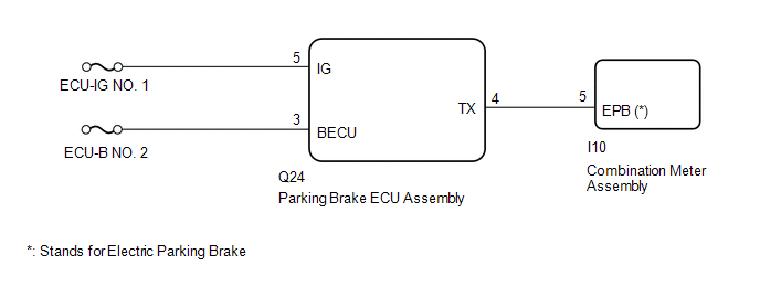
WIRING DIAGRAM
CAUTION / NOTICE / HINT
NOTICE:
- Inspect the fuses for circuits related to this system before performing the following inspection procedure.
- Before disconnecting connectors or fuses, turn the power switch off and wait 20 seconds or more.
- When replacing the parking brake ECU assembly, operate the electric parking brake switch (integration control and panel assembly), as the parking brake indicator light (red) blinks when the power switch is first turned on (IG).
HINT:
The condition may be that the electric parking brake is operating normally but the meter parking brake indicator light (red) is malfunctioning.
PROCEDURE
| 1. | VEHICLE OPERATION CHECK |
(a) Turn the power switch on (READY) and move the shift lever to D. Then depress the brake pedal and pull the electric parking brake switch (integration control and panel assembly) to the lock side for 1 second. Check the parking brake indicator light (red) condition.
(b) Release the brake pedal and check that the vehicle does not move.
(c) Depress the brake pedal and push the electric parking brake switch (integration control and panel assembly) to the release side for 1 second. Check the parking brake indicator light (red) condition.
(d) Release the brake pedal and check that the vehicle moves.
| Result | Proceed to |
|---|---|
| Lock and release control is normal; parking brake indicator light (red) is off or is blinking | A |
| Lock and release control is malfunctioning; parking brake indicator light (red) is illuminated or off depending on switch operation | B |
| Lock and release control is malfunctioning; parking brake indicator light (red) is off or is blinking | C |
| B | .gif) | INSPECT REAR BRAKE |
| C | | GO TO STEP 4 |
|
.gif)
| 2. | PERFORM ACTIVE TEST USING TECHSTREAM (PKB LIGHT) |
(a) Turn the power switch off.
(b) Connect the Techstream to the DLC3.
(c) Turn the power switch on (IG) and the Techstream on.
(d) Enter the following menus: Chassis / Electric Parking Brake / Active Test.
(e) Check the condition of the parking brake indicator light (red) by operating the Techstream.
Chassis > Electric Parking Brake > Active Test| Tester Display | Measurement Item | Control Range | Diagnostic Note |
|---|---|---|---|
| PKB Light | Parking brake indicator light (red) | ON or OFF |
|
| Tester Display |
|---|
| PKB Light |
OK:
Indicator light turns on when operating the Techstream.
| OK | | REPLACE PARKING BRAKE ECU ASSEMBLY |
.gif)
|
| 3. | CHECK HARNESS AND CONNECTOR (PARKING BRAKE ECU ASSEMBLY - COMBINATION METER ASSEMBLY) |
(a) Turn the power switch off.
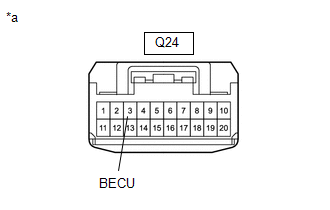
(b) Disconnect the Q24 parking brake ECU assembly connector.
(c) Disconnect the I10 combination meter assembly connector.
(d) Measure the resistance according to the value(s) in the table below.
Standard Resistance:
| Tester Connection | Condition | Specified Condition |
|---|---|---|
| Q24-4 (TX) - I10-5 (EPB)* | Always | Below 1 Ω |
| Q24-4 (TX) or I10-5 (EPB)* - Body ground | Always | 10 kΩ or higher |
HINT:
*: Stands for electric parking brake
| OK | | GO TO METER / GAUGE SYSTEM |
| NG | | REPAIR OR REPLACE HARNESS OR CONNECTOR |
| 4. | CHECK HARNESS AND CONNECTOR (AUXILIARY BATTERY - PARKING BRAKE ECU ASSEMBLY) |
(a) Turn the power switch off.
| (b) Disconnect the parking brake ECU assembly connector. |
|
(c) Measure the voltage according to the value(s) in the table below.
Standard Voltage:
| Tester Connection | Condition | Specified Condition |
|---|---|---|
| Q24-3 (BECU) - Body ground | Always | 11 to 14 V |
| NG | | REPAIR OR REPLACE HARNESS OR CONNECTOR |
|
| 5. | CHECK HARNESS AND CONNECTOR (AUXILIARY BATTERY - PARKING BRAKE ECU ASSEMBLY) |
(a) Turn the power switch off.
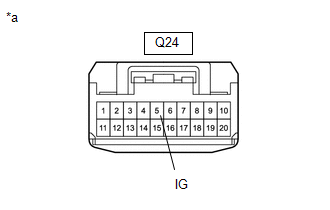
| (b) Disconnect the parking brake ECU assembly connector. |
|
(c) Measure the voltage according to the value(s) in the table below.
Standard Voltage:
| Tester Connection | Switch Condition | Specified Condition |
|---|---|---|
| Q24-5 (IG) - Body ground | Power switch on (IG) | 11 to 14 V |
| OK | | REPLACE PARKING BRAKE ECU ASSEMBLY |
| NG | | REPAIR OR REPLACE HARNESS OR CONNECTOR |
READ NEXT:
 Electric Parking Brake System AUTO Function Circuit
DESCRIPTION The parking brake ECU assembly receives shift position information from the hybrid vehicle control ECU via CAN communication. Also, the parking brake ECU assembly receives wheel speed info
Electric Parking Brake AUTO Indicator Light Circuit
WIRING DIAGRAM CAUTION / NOTICE / HINT NOTICE:
Inspect the fuses for circuits related to this system before performing the following inspection procedure.
Before disconnecting connectors or fuse
Forced Release
Operation MethodOPERATION METHOD PROCEDURE 1. PARKING BRAKE FORCED RELEASE NOTICE: Follow the procedures when using SST to release the parking brake. If the parking brake cannot be released, follow t
SEE MORE:
Dtc Check / Clear
DTC CHECK / CLEAR CHECK DTC (a) Connect the Techstream to the DLC3. (b) Turn the power switch on (IG). (c) Turn the Techstream on. (d) Enter the following menus: Body Electrical / Smart Access / Trouble Codes. Body Electrical > Smart Access > Trouble Codes (e) Check the details of the DTCs. Cl
For your information
Main Owner's Manual
Please note that this manual applies to
all models and explains all equipment,
including options. Therefore, you may
find some explanations for equipment
not installed on your vehicle.
All specifications provided in this manual
are current at the time of printing.
How
