Lexus NX: Engine Oil Cooler
Components
COMPONENTS
ILLUSTRATION
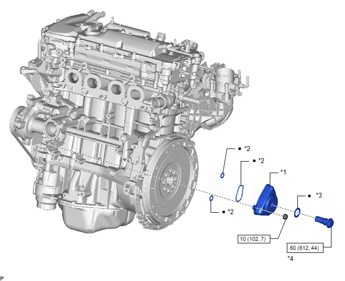
| *1 | OIL COOLER ASSEMBLY | *2 | GASKET |
| *3 | SEAL WASHER | *4 | UNION BOLT |
.png) | N*m (kgf*cm, ft.*lbf): Specified torque | ● | Non-reusable part |
Removal
REMOVAL
PROCEDURE
1. REMOVE EXHAUST MANIFOLD CONVERTER SUB-ASSEMBLY
Click here .gif)
2. DRAIN ENGINE OIL
Click here
3. DRAIN ENGINE COOLANT
Click here
4. REMOVE OIL COOLER ASSEMBLY
| (a) Remove the nut, union bolt, seal washer and oil cooler assembly. |
|
(b) Remove the 3 gaskets from the oil cooler assembly.
Inspection
INSPECTION
PROCEDURE
1. INSPECT OIL COOLER ASSEMBLY
(a) Visually check the oil cooler assembly for cracks or damage.
If cracks or damage is found, replace the oil cooler assembly.
Installation
INSTALLATION
PROCEDURE
1. INSTALL OIL COOLER ASSEMBLY
(a) Clean the oil cooler assembly contact surface on the oil cooler assembly mounting.
(b) Apply a light coat of engine oil to 3 new gaskets.
(c) Install the 3 gaskets to the oil cooler assembly.
(d) Temporarily install the oil cooler assembly with the union bolt, the nut and a new seal washer.
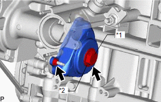
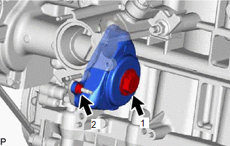
| (e) Tighten the union bolt and nut in several steps in the sequence shown in the illustration. Torque: Union bolt : 60 N·m {612 kgf·cm, 44 ft·lbf} Nut : 10 N·m {102 kgf·cm, 7 ft·lbf} |
|
2. INSTALL EXHAUST MANIFOLD CONVERTER SUB-ASSEMBLY
Click here .gif)
3. ADD ENGINE OIL
Click here
4. ADD ENGINE COOLANT
Click here
5. INSPECT ENGINE OIL LEVEL
Click here
6. INSPECT FOR OIL LEAK
Click here
7. INSPECT FOR COOLANT LEAK
Click here
READ NEXT:
 Lubrication System
On-vehicle InspectionON-VEHICLE INSPECTION PROCEDURE 1. INSPECT ENGINE OIL LEVEL (a) Put the engine in inspection mode (maintenance mode). Click here (b) Warm up and stop the engine 5 minutes later
Components
COMPONENTS ILLUSTRATION *1 OIL FILTER CAP ASSEMBLY *2 O-RING *3 GASKET *4 OIL PAN DRAIN PLUG *5 OIL FILTER ELEMENT *6 OIL FILTER DRAIN PLUG *7 OIL FILLER CAP -
SEE MORE:
Installation
INSTALLATION CAUTION / NOTICE / HINT CAUTION: Wear protective gloves. Sharp areas on the parts may injure your hands. PROCEDURE 1. INSTALL BENCH TYPE REAR SEAT CUSHION COVER (REAR SEAT CUSHION HEATER) HINT:
When installing the seat cover, refer to the precautions in order to prevent wrinkles from
Black Screen
PROCEDURE 1. CHECK DISPLAY SETTING (a) Check that the display is not in screen off mode. OK: The display setting is not in screen off mode. NG CHANGE SCREEN TO SCREEN ON MODE
OK 2. CHECK IMAGE QUALITY SETTING (a) Check that the display settings (contrast,
