Lexus NX: Vehicle Speed Signal Circuit between Radio Receiver and Combination Meter
DESCRIPTION
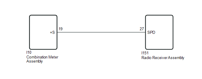
The radio receiver assembly receives a vehicle speed signal from the combination meter assembly to control the ASL function.
HINT:
- A voltage of 12 V or 5 V is output from each ECU and then input to the combination meter assembly. The signal is changed to a pulse signal at the transistor in the combination meter assembly. Each ECU controls its respective system based on this pulse signal.
- If a short occurs in any of the ECUs or in the wire harness connected to an ECU, all systems in the diagram below will not operate normally.
WIRING DIAGRAM
PROCEDURE
| 1. | CHECK COMBINATION METER ASSEMBLY (OUTPUT WAVEFORM) |
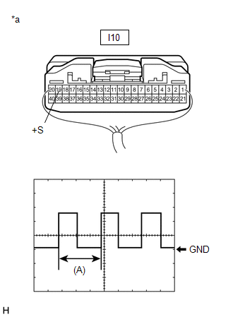
| (a) Check the output waveform. (1) Remove the combination meter assembly with the connector still connected. (2) Connect an oscilloscope to terminal I10-19 (+S) and body ground. (3) Turn the power switch on (IG). (4) Turn a wheel slowly. (5) Check the signal waveform according to the condition(s) in the table below.
OK: The waveform is similar to that shown in the illustration. HINT: When the system is functioning normally, one wheel revolution generates 4 pulses. As the vehicle speed increases, the width indicated by (A) in the illustration narrows. |
|
| NG | .gif) | GO TO METER / GAUGE SYSTEM |
|
.gif)
| 2. | CHECK HARNESS AND CONNECTOR (RADIO RECEIVER ASSEMBLY - COMBINATION METER ASSEMBLY) |
(a) Disconnect the I151 radio receiver assembly connector.
(b) Disconnect the I10 combination meter assembly connector.
(c) Measure the resistance according to the value(s) in the table below.
Standard Resistance:
| Tester Connection | Condition | Specified Condition |
|---|---|---|
| I151-27 (SPD) - I10-19 (+S) | Always | Below 1 Ω |
| OK | | PROCEED TO NEXT SUSPECTED AREA SHOWN IN PROBLEM SYMPTOMS TABLE |
.gif)
| NG | | REPAIR OR REPLACE HARNESS OR CONNECTOR |
READ NEXT:
 Steering Pad Switch Circuit
DESCRIPTION This circuit sends an operation signal from the steering pad switch assembly to the radio receiver assembly. If there is an open in the circuit, the audio system cannot be operated using t
Illumination Circuit
DESCRIPTION Power is supplied to the radio receiver assembly and steering pad switch assembly when the light control switch is in the tail or head position. WIRING DIAGRAM CAUTION / NOTICE / HINT NOT
Speaker Circuit
DESCRIPTION If there is a short in a speaker circuit, the stereo component amplifier assembly detects it and stops output to the speakers. As a result, sound cannot be heard from the speakers even if
SEE MORE:
Installation
INSTALLATION PROCEDURE 1. INSPECT COMPRESSOR OIL (a) When replacing the compressor assembly with motor with a new one, gradually discharge the inert gas from the service valve, and drain the following amount of oil from the new compressor assembly with motor before installation. Standard: (Oil c
Intake System
On-vehicle InspectionON-VEHICLE INSPECTION PROCEDURE 1. INSPECT INTAKE SYSTEM HINT: Perform "Inspection After Repair" after repairing air leaks in the intake system. Click here (a) Check that there are no vacuum leaks at the points shown in the illustration.
