- Open in mass air flow meter sub-assembly power source circuit
- Open or short in VG circuit
Lexus NX: Mass Air Flow Circuit Low (P0102,P0103)
Lexus NX Service Manual / Engine & Hybrid System / 2ar-fxe (engine Control) / Sfi System / Mass Air Flow Circuit Low (P0102,P0103)
DESCRIPTION
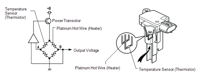
The mass air flow meter sub-assembly is a sensor that measures the amount of air flowing through the throttle valve. The ECM uses this information to determine the fuel injection duration and to provide an appropriate air fuel ratio. Inside the mass air flow meter sub-assembly, there is a heated platinum wire which is exposed to the flow of intake air. By applying a specific electrical current to the wire, the ECM heats it to a specific temperature. The flow of incoming air cools both the wire and an internal thermistor, affecting their resistance. To maintain a constant current value, the ECM varies the voltage applied to the wire and internal thermistor. The voltage level is proportional to the airflow through the sensor, and the ECM uses it to calculate the intake air volume.
The circuit is constructed so that the platinum hot wire and the temperature sensor create a bridge circuit, and the power transistor is controlled so that the potentials of A and B remain equal to maintain the predetermined temperature.
HINT:
When any of these DTCs are stored, the ECM enters fail-safe mode. During fail-safe mode, the ignition timing is calculated by the ECM, according to the engine speed and throttle valve position. Fail-safe mode continues until a pass condition is detected.
| DTC No. | Detection Item | DTC Detection Condition | Trouble Area | MIL | Memory |
|---|---|---|---|---|---|
| P0102 | Mass Air Flow Circuit Low | The mass air flow meter sub-assembly voltage is less than 0.2 V for 3 seconds. (1 trip detection logic: Engine speed is less than 4000 rpm) (2 trip detection logic: Engine speed is 4000 rpm or higher) |
| Comes on | DTC stored |
| P0103 | Mass Air Flow Circuit High | The mass air flow meter sub-assembly voltage is higher than 4.9 V for 3 seconds. (1 trip detection logic: Engine speed is less than 4000 rpm) (2 trip detection logic: Engine speed is 4000 rpm or higher) |
| Comes on | DTC stored |
HINT:
When any of these DTCs are output, check the air flow rate by using the Techstream. Enter the following menus: Powertrain / Engine and ECT / Data List / Primary / MAF.
| Mass Air Flow Rate (gm/sec) | Malfunction |
|---|---|
| Approximately 0.0 | |
| 271.0 or more |
|
MONITOR DESCRIPTION
If there is a defect or an open or short circuit in the mass air flow meter sub-assembly, the voltage level deviates from the normal operating range. The ECM interprets this deviation as a malfunction in the mass air flow meter sub-assembly circuit and stores a DTC.
Example:
When the sensor output voltage remains less than 0.2 V, or higher than 4.9 V for 3 seconds, the ECM stores a DTC.
MONITOR STRATEGY
| Related DTCs | P0102: Mass air flow meter range check (low voltage) P0103: Mass air flow meter range check (high voltage) |
| Required Sensors/Components (Main) | Mass air flow meter sub-assembly |
| Required Sensors/Components (Related) | Crankshaft position sensor |
| Frequency of Operation | Continuous |
| Duration | 3 seconds |
| MIL Operation | Immediate: Engine speed less than 4000 rpm 2 driving cycles: Engine speed 4000 rpm or higher |
| Sequence of Operation | None |
TYPICAL ENABLING CONDITIONS
| Monitor runs whenever the following DTCs are not stored | None |
TYPICAL MALFUNCTION THRESHOLDS
P0102| Mass air flow meter voltage | Less than 0.2 V |
| Mass air flow meter voltage | Higher than 4.9 V |
COMPONENT OPERATING RANGE
| Mass air flow meter voltage | 0.2 to 4.9 V |
CONFIRMATION DRIVING PATTERN
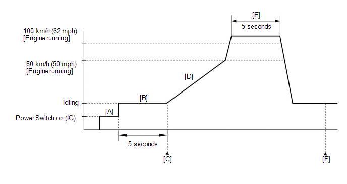
- Connect the Techstream to the DLC3.
- Turn the power switch on (IG) and turn the Techstream on.
- Clear the DTCs (even if no DTCs are stored, perform the clear DTC procedure).
- Turn the power switch off and wait for at least 30 seconds.
- Turn the power switch on (IG) and turn the Techstream on [A].
-
Put the engine in inspection mode (maintenance mode).
Click here
.gif)
- Start the engine.
- Idle the engine for 5 seconds [B].
- Enter the following menus: Powertrain / Engine and ECT / Trouble Codes [C].
-
Read the pending DTCs.
HINT:
- If a pending DTC is output, the system is malfunctioning.
- If a pending DTC is not output, perform the following procedure.
-
With the engine running, during normal driving, increase the vehicle speed to 80 km/h (50 mph) [D].
CAUTION:
When performing the confirmation driving pattern, obey all speed limits and traffic laws.
HINT:
If the engine stops, further depress the accelerator pedal to restart the engine.
-
With the engine running, depress the accelerator pedal fully to increase the vehicle speed to between 100 and 120 km/h (62 and 75 mph) (engine speed of 4000 rpm or more) and then maintain the speed for at least 5 seconds [E].
CAUTION:
When performing the confirmation driving pattern, obey all speed limits and traffic laws.
HINT:
If the engine stops, further depress the accelerator pedal to restart the engine.
- Enter the following menus: Powertrain / Engine and ECT / Trouble Codes [F].
-
Read the pending DTCs.
HINT:
- If a pending DTC is output, the system is malfunctioning.
- If a pending DTC is not output, perform the following procedure.
- Enter the following menus: Powertrain / Engine and ECT / Utility / All Readiness.
- Input the DTC: P0102 or P0103.
-
Check the DTC judgment result.
Techstream Display
Description
NORMAL
- DTC judgment completed
- System normal
ABNORMAL
- DTC judgment completed
- System abnormal
INCOMPLETE
- DTC judgment not completed
- Perform driving pattern after confirming DTC enabling conditions
N/A
- Unable to perform DTC judgment
- Number of DTCs which do not fulfill DTC preconditions has reached ECU memory limit
HINT:
- If the judgment result shows NORMAL, the system is normal.
- If the judgment result shows ABNORMAL, the system has a malfunction.
- If the judgment result shows INCOMPLETE or N/A, perform steps [B] through [F] again.
-
If no pending DTC is output, perform a universal trip and check for permanent DTCs.
Click here
HINT:
- If a permanent DTC is output, the system is malfunctioning.
- If no permanent DTC is output, the system is normal.
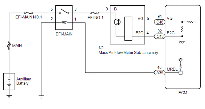
WIRING DIAGRAM
CAUTION / NOTICE / HINT
NOTICE:
Inspect the fuses for circuits related to this system before performing the following procedure.
HINT:
Read freeze frame data using the Techstream. The ECM records vehicle and driving condition information as freeze frame data the moment a DTC is stored. When troubleshooting, freeze frame data can help determine if the vehicle was moving or stationary, if the engine was warmed up or not, if the air fuel ratio was lean or rich, and other data from the time the malfunction occurred.
PROCEDURE
| 1. | READ OUTPUT DTC (DTC P0102 OR P0103) |
(a) Connect the Techstream to the DLC3.
(b) Turn the power switch on (IG).
(c) Turn the Techstream on.
(d) Enter the following menus: Powertrain / Engine and ECT / Trouble Codes.
(e) Read the DTCs.
Powertrain > Engine and ECT > Trouble Codes| Result | Proceed to |
|---|---|
| DTC P0102 is output | A |
| DTC P0103 is output | B |
| B | .gif) | GO TO STEP 6 |
|
.gif)
| 2. | CHECK TERMINAL VOLTAGE (POWER SOURCE OF MASS AIR FLOW METER SUB-ASSEMBLY) |
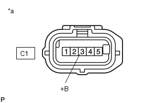
| *a | Front view of wire harness connector (to Mass Air Flow Meter Sub-assembly) |
(a) Disconnect the mass air flow meter sub-assembly connector.
(b) Turn the power switch on (IG).
(c) Measure the voltage according to the value(s) in the table below.
Standard Voltage:
| Tester Connection | Condition | Specified Condition |
|---|---|---|
| C1-3 (+B) - Body ground | Power switch on (IG) | 11 to 14 V |
| NG | | GO TO STEP 5 |
|
| 3. | CHECK HARNESS AND CONNECTOR (MASS AIR FLOW METER SUB-ASSEMBLY - ECM) |
(a) Disconnect the mass air flow meter sub-assembly connector.
(b) Disconnect the ECM connector.
(c) Measure the resistance according to the value(s) in the table below.
Standard Resistance:
| Tester Connection | Condition | Specified Condition |
|---|---|---|
| C1-5 (VG) - C48-91 (VG) | Always | Below 1 Ω |
| C1-4 (E2G) - C48-92 (E2G) | Always | Below 1 Ω |
| C1-5 (VG) or C48-91 (VG) - Body ground | Always | 10 kΩ or higher |
| NG | | REPAIR OR REPLACE HARNESS OR CONNECTOR |
|
| 4. | INSPECT MASS AIR FLOW METER SUB-ASSEMBLY |
(a) Inspect the mass air flow meter sub-assembly, referring to the On-vehicle Inspection for Mass Air Flow Meter.
Click here
(b) Inspect the mass air flow meter sub-assembly, referring to the Inspection for Mass Air Flow Meter.
Click here
(c) Inspect the function of the mass air flow meter sub-assembly.
(1) Connect the Techstream to the DLC3.
(2) Turn the power switch on (IG).
(3) Turn the Techstream on.
(4) Put the engine in inspection mode (maintenance mode).
Click here
| Tester Display |
|---|
| Inspection Mode |
(5) Enter the following menus: Powertrain / Engine and ECT / Data List / Primary / MAF.
Powertrain > Engine and ECT > Data List| Tester Display |
|---|
| MAF |
(6) Start the engine.
(7) Check that the MAF value changes when the engine is raced.
OK:
The reading changes.
HINT:
Perform "Inspection After Repair" after replacing the mass air flow meter sub-assembly.
Click here
| OK | | REPLACE ECM |
| NG | | REPLACE MASS AIR FLOW METER SUB-ASSEMBLY |
| 5. | CHECK HARNESS AND CONNECTOR (MASS AIR FLOW METER SUB-ASSEMBLY - EFI-MAIN RELAY) |
(a) Disconnect the mass air flow meter sub-assembly connector.
(b) Remove the EFI-MAIN relay from the No. 1 engine room relay block and junction block assembly.
(c) Measure the resistance according to the value(s) in the table below.
Standard Resistance:
| Tester Connection | Condition | Specified Condition |
|---|---|---|
| C1-3 (+B) - 3 (EFI-MAIN Relay) | Always | Below 1 Ω |
| C1-3 (+B) or 3 (EFI-MAIN Relay) - Body ground | Always | 10 kΩ or higher |
| OK | | GO TO ECM POWER SOURCE CIRCUIT |
| NG | | REPAIR OR REPLACE HARNESS OR CONNECTOR |
| 6. | CHECK HARNESS AND CONNECTOR (SENSOR GROUND) |
(a) Disconnect the mass air flow meter sub-assembly connector.
(b) Measure the resistance according to the value(s) in the table below.
Standard Resistance:
| Tester Connection | Condition | Specified Condition |
|---|---|---|
| C1-4 (E2G) - Body ground | Always | Below 1 Ω |
HINT:
Perform "Inspection After Repair" after replacing the mass air flow meter sub-assembly.
Click here
| OK | | REPLACE MASS AIR FLOW METER SUB-ASSEMBLY |
|
| 7. | CHECK HARNESS AND CONNECTOR (MASS AIR FLOW METER SUB-ASSEMBLY - ECM) |
(a) Disconnect the mass air flow meter sub-assembly connector.
(b) Disconnect the ECM connector.
(c) Measure the resistance according to the value(s) in the table below.
Standard Resistance:
| Tester Connection | Condition | Specified Condition |
|---|---|---|
| C1-4 (E2G) - C48-92 (E2G) | Always | Below 1 Ω |
| OK | | REPLACE ECM |
| NG | | REPAIR OR REPLACE HARNESS OR CONNECTOR |
READ NEXT:
 Manifold Absolute Pressure Circuit Problem (P0106)
DESCRIPTION The manifold absolute pressure sensor detects pressure inside the intake manifold as an absolute pressure with a built-in sensor and outputs it as voltage. Based on the voltage from the m
Manifold Absolute Pressure / Barometric Pressure Circuit Low Input (P0107,P0108)
DESCRIPTION The manifold absolute pressure sensor detects the intake manifold pressure as a change in voltage. The ECM calculates the intake manifold pressure based on this voltage. The ECM calculate
Intake Air Temperature Sensor 1 Circuit Range / Performance (P0111)
DESCRIPTION Refer to DTC P0112. Click here DTC No. Detection Item DTC Detection Condition Trouble Area MIL Memory P0111 Intake Air Temperature Sensor 1 Circuit Range / Performance
SEE MORE:
Components
COMPONENTS ILLUSTRATION *1 NO. 1 ENGINE UNDER COVER ASSEMBLY - - ILLUSTRATION *1 FRONT ENGINE MOUNTING BRACKET *2 HYBRID VEHICLE TRANSAXLE ASSEMBLY *3 NO. 1 MOTOR WATER JACKET COVER ASSEMBLY *4 NO. 1 TRANSMISSION CONTROL CABLE BRACKET *5 NO. 2 AUTOMATIC TRANSMI
System Description
SYSTEM DESCRIPTION ASC SYSTEM (a) The ASC system uses a stereo component equalizer assembly to electronically generate a driving sound. Simulated engine sounds are output from the No. 1 speaker assembly with box. The simulated engine sounds are calculated based on the vehicle information (driving mo
© 2016-2026 Copyright www.lexunx.com
