Lexus NX: Front Fog Light Circuit
DESCRIPTION
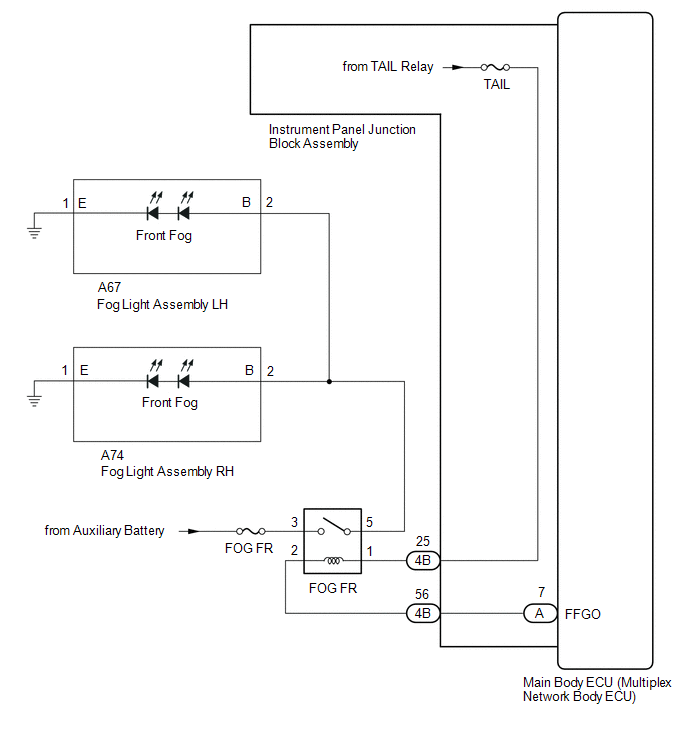
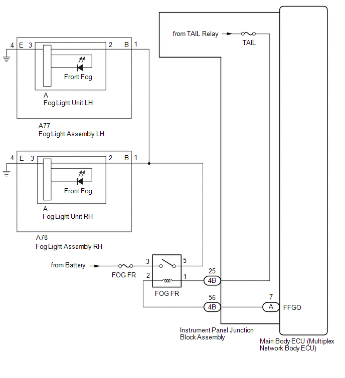
Illumination of the front fog lights is controlled by the main body ECU (multiplex network body ECU).
WIRING DIAGRAM
except Sport Package:
for Sport Package:
CAUTION / NOTICE / HINT
NOTICE:
- Inspect the fuses for circuits related to this system before performing the following inspection procedure.
- Before performing troubleshooting, check that the taillight circuit operates properly.
- Recognition code registration is necessary when replacing the main body ECU (multiplex network body ECU).
-
If the main body ECU (multiplex network body ECU) is replaced, refer to Registration.
Click here
.gif)
PROCEDURE
| 1. | PERFORM ACTIVE TEST USING TECHSTREAM (FRONT FOG LIGHT RELAY) |
(a) Using the Techstream, perform the Active Test.
Click here
| Tester Display | Measurement Item | Control Range | Diagnostic Note |
|---|---|---|---|
| Front Fog Light Relay | Front fog light relay | ON or OFF | The headlight dimmer switch is in the tail position |
| Tester Display |
|---|
| Front Fog Light Relay |
| Result | Proceed to |
|---|---|
| The Active Test is performed normally | A |
| The Active Test is not performed normally for both fog lights | B |
| The Active Test is not performed normally for the right side fog light only (except Sport Package) | C |
| The Active Test is not performed normally for the left side fog light only (except Sport Package) | D |
| The Active Test is not performed normally for the right side fog light only (for Sport Package) | E |
| The Active Test is not performed normally for the left side fog light only (for Sport Package) | F |
| A | .gif) | PROCEED TO NEXT SUSPECTED AREA SHOWN IN PROBLEM SYMPTOMS TABLE |
| C | | GO TO STEP 9 |
| D | | GO TO STEP 10 |
| E | | GO TO STEP 11 |
| F | | GO TO STEP 13 |
|
.gif)
| 2. | CHECK FRONT FOG LIGHT RELAY (FOG FR) |
(a) Remove the front fog light relay from the No. 2 engine room relay block.
(b) Inspect the fog light relay.
Click here
| NG | | REPLACE FOG LIGHT RELAY (FOG FR) |
|
| 3. | CHECK HARNESS AND CONNECTOR (FRONT FOG LIGHT RELAY [FOG FR] - BATTERY) |
| (a) Remove the front fog light relay from the No. 2 engine room relay block. |
|
.png)
(b) Measure the voltage according to the value(s) in the table below.
Standard Voltage:
| Tester Connection | Switch Condition | Specified Condition |
|---|---|---|
| Relay terminal 3 - Body ground | Power switch off | 11 to 14 V |
| NG | | REPAIR OR REPLACE HARNESS OR CONNECTOR |
|
| 4. | CHECK HARNESS AND CONNECTOR (TAILLIGHT RELAY [TAIL RELAY] - FRONT FOG LIGHT RELAY [FOG FR]) |
| (a) Remove the front fog light relay from the No. 2 engine room relay block. |
|
.png)
(b) Measure the voltage according to the value(s) in the table below.
Standard Voltage:
| Tester Connection | Switch Condition | Specified Condition |
|---|---|---|
| If the low beams are illuminated, shine a light on the automatic light control sensor to change the system to daytime mode. | ||
| Relay terminal 1 - Body ground | Headlight dimmer switch in AUTO with low beams off → low beams on | Below 1 V → 11 to 14 V |
| NG | | GO TO STEP 7 |
|
| 5. | CHECK HARNESS AND CONNECTOR (FRONT FOG LIGHT RELAY [FOG FR] - FOG LIGHT ASSEMBLY AND BODY GROUND) |
(a) Remove the front fog light relay from the No. 2 engine room relay block.
(b) Disconnect the A67 fog light assembly LH connector.
(c) Disconnect the A74 fog light assembly RH connector.
(d) Measure the resistance according to the value(s) in the table below.
Standard Resistance:
| Tester Connection | Condition | Specified Condition |
|---|---|---|
| Relay terminal 5 - A67-2 (B) | Always | Below 1 Ω |
| Relay terminal 5 - A74-2 (B) | Always | Below 1 Ω |
| A67-1 (E) - Body ground | Always | Below 1 Ω |
| A74-1 (E) - Body ground | Always | Below 1 Ω |
| Relay terminal 5 or A67-2 (B) - Body ground | Always | 10 kΩ or higher |
| Relay terminal 5 or A74-2 (B) - Body ground | Always | 10 kΩ or higher |
| NG | | REPAIR OR REPLACE HARNESS OR CONNECTOR |
|
| 6. | CHECK HARNESS AND CONNECTOR (FRONT FOG LIGHT RELAY [FOG FR] - MAIN BODY ECU [MULTIPLEX NETWORK BODY ECU]) |
(a) Remove the front fog light relay from the No. 2 engine room relay block.
(b) Remove the instrument panel junction block assembly.
Click here
(c) Remove the main body ECU (multiplex network body ECU) from the instrument panel junction block assembly.
Click here
(d) Disconnect the 4B instrument panel junction block assembly connector.
(e) Measure the resistance according to the value(s) in the table below.
Standard Resistance:
| Tester Connection | Condition | Specified Condition |
|---|---|---|
| Relay terminal 2 - A-7 (FFGO) | Always | Below 1 Ω |
| Relay terminal 2 or A-7 (FFGO) - Body ground | Always | 10 kΩ or higher |
| OK | | REPLACE MAIN BODY ECU (MULTIPLEX NETWORK BODY ECU) |
| NG | | GO TO STEP 8 |
| 7. | CHECK HARNESS AND CONNECTOR (FRONT FOG LIGHT RELAY [FOG FR] - INSTRUMENT PANEL JUNCTION BLOCK ASSEMBLY) |
(a) Remove the front fog light relay from the No. 2 engine room relay block.
(b) Disconnect the 4B instrument panel junction block assembly connector.
(c) Measure the resistance according to the value(s) in the table below.
Standard Resistance:
| Tester Connection | Condition | Specified Condition |
|---|---|---|
| Relay terminal 1 - 4B-25 | Always | Below 1 Ω |
| Relay terminal 1 or 4B-25 - Body ground | Always | 10 kΩ or higher |
| OK | | REPLACE INSTRUMENT PANEL JUNCTION BLOCK ASSEMBLY |
| NG | | REPAIR OR REPLACE HARNESS OR CONNECTOR |
| 8. | CHECK HARNESS AND CONNECTOR (FRONT FOG LIGHT RELAY [FOG FR] - INSTRUMENT PANEL JUNCTION BLOCK ASSEMBLY) |
(a) Remove the front fog light relay from the No. 2 engine room relay block.
(b) Disconnect the 4B instrument panel junction block assembly connector.
(c) Measure the resistance according to the value(s) in the table below.
Standard Resistance:
| Tester Connection | Condition | Specified Condition |
|---|---|---|
| Relay terminal 2 - 4B-56 | Always | Below 1 Ω |
| Relay terminal 2 or 4B-56 - Body ground | Always | 10 kΩ or higher |
| OK | | REPLACE INSTRUMENT PANEL JUNCTION BLOCK ASSEMBLY |
| NG | | REPAIR OR REPLACE HARNESS OR CONNECTOR |
| 9. | CHECK HARNESS AND CONNECTOR (FRONT FOG LIGHT RELAY [FOG FR] - FOG LIGHT ASSEMBLY RH) |
(a) Remove the front fog light relay from the No. 2 engine room relay block.
(b) Disconnect the A74 fog light assembly RH connector.
(c) Measure the resistance according to the value(s) in the table below.
Standard Resistance:
| Tester Connection | Condition | Specified Condition |
|---|---|---|
| Relay terminal 5 - A74-2 (B) | Always | Below 1 Ω |
| A74-1 (E) - Body ground | Always | Below 1 Ω |
| Relay terminal 5 or A74-2 (B) - Body ground | Always | 10 kΩ or higher |
| OK | | REPLACE FOG LIGHT ASSEMBLY RH |
| NG | | REPAIR OR REPLACE HARNESS OR CONNECTOR |
| 10. | CHECK HARNESS AND CONNECTOR (FRONT FOG LIGHT RELAY [FOG FR] - FOG LIGHT ASSEMBLY LH) |
(a) Remove the front fog light relay from the No. 2 engine room relay block.
(b) Disconnect the A67 fog light assembly LH connector.
(c) Measure the resistance according to the value(s) in the table below.
Standard Resistance:
| Tester Connection | Condition | Specified Condition |
|---|---|---|
| Relay terminal 5 - A67-2 (B) | Always | Below 1 Ω |
| A67-1 (E) - Body ground | Always | Below 1 Ω |
| Relay terminal 5 or A67-2 (B) - Body ground | Always | 10 kΩ or higher |
| OK | | REPLACE FOG LIGHT ASSEMBLY LH |
| NG | | REPAIR OR REPLACE HARNESS OR CONNECTOR |
| 11. | CHECK HARNESS AND CONNECTOR (FRONT FOG LIGHT RELAY [FOG FR] - FOG LIGHT ASSEMBLY RH) |
(a) Remove the front fog light relay from the No. 2 engine room relay block.
(b) Disconnect the A78 fog light assembly RH connector.
(c) Measure the resistance according to the value(s) in the table below.
Standard Resistance:
| Tester Connection | Condition | Specified Condition |
|---|---|---|
| Relay terminal 5 - A78-1 (B) | Always | Below 1 Ω |
| A78-4 (E) - Body ground | Always | Below 1 Ω |
| Relay terminal 5 or A78-1 (B) - Body ground | Always | 10 kΩ or higher |
| NG | | REPAIR OR REPLACE HARNESS OR CONNECTOR |
|
| 12. | INSPECT FOG LIGHT ASSEMBLY RH |
| (a) Remove the fog light assembly RH. Click here |
|
(b) Remove the fog light unit RH from the fog light assembly RH.
Click here
(c) Measure the resistance according to the value(s) in the table below.
Standard Resistance:
| Tester Connection | Condition | Specified Condition |
|---|---|---|
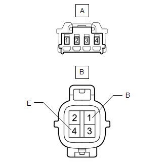
| A-2 - B-1 (B) | Always | Below 1 Ω |
| A-3 - B-4 (E) | Always | 10 kΩ or higher |
| OK | | REPLACE FOG LIGHT UNIT RH |
| NG | | REPLACE FOG LIGHT ASSEMBLY RH |
| 13. | CHECK HARNESS AND CONNECTOR (FRONT FOG LIGHT RELAY [FOG FR] - FOG LIGHT ASSEMBLY LH) |
(a) Remove the front fog light relay from the No. 2 engine room relay block.
(b) Disconnect the A77 fog light assembly LH connector.
(c) Measure the resistance according to the value(s) in the table below.
Standard Resistance:
| Tester Connection | Condition | Specified Condition |
|---|---|---|
| Relay terminal 5 - A77-1 (B) | Always | Below 1 Ω |
| A77-4 (E) - Body ground | Always | Below 1 Ω |
| Relay terminal 5 or A77-1 (B) - Body ground | Always | 10 kΩ or higher |
| NG | | REPAIR OR REPLACE HARNESS OR CONNECTOR |
|
| 14. | INSPECT FOG LIGHT ASSEMBLY LH |
| (a) Remove the fog light assembly LH. Click here |
|
(b) Remove the fog light unit LH from the fog light assembly LH.
Click here
(c) Measure the resistance according to the value(s) in the table below.
Standard Resistance:
| Tester Connection | Condition | Specified Condition |
|---|---|---|
| A-2 - B-1 (B) | Always | Below 1 Ω |
| A-3 - B-4 (E) | Always | 10 kΩ or higher |
| OK | | REPLACE FOG LIGHT UNIT LH |
| NG | | REPLACE FOG LIGHT ASSEMBLY LH |
READ NEXT:
 Hazard Warning Switch Circuit
DESCRIPTION When the combination meter receives a hazard warning signal switch signal, the flasher IC turns on and hazard control is performed. WIRING DIAGRAM CAUTION / NOTICE / HINT NOTICE: When rep
Taillight Relay Circuit
DESCRIPTION Illumination of the taillights and license plate light is controlled by the main body ECU (multiplex network body ECU). WIRING DIAGRAM CAUTION / NOTICE / HINT NOTICE:
Inspect the fuse
Power Source Circuit
DESCRIPTION The main body ECU (multiplex network body ECU) receives IG signals and supplies power to the headlight ECU sub-assembly via the H-LP relay. WIRING DIAGRAM CAUTION / NOTICE / HINT NOTICE:
SEE MORE:
Components
COMPONENTS ILLUSTRATION *1 INSTRUMENT SIDE PANEL LH *2 NO. 1 INSTRUMENT PANEL SAFETY PAD SUB-ASSEMBLY *3 TRIP SWITCH (LIGHT CONTROL RHEOSTAT) - -
Diagnostic Trouble Code Chart
DIAGNOSTIC TROUBLE CODE CHART Power Window Control System DTC No. Detection Item Link B2311 Power Window Motor Malfunction B2311 Power Window Motor Malfunction B2311 Power Window Motor Malfunction B2311 Power Window Motor Malfunction B2312 Pow
