Lexus NX: Taillight Relay Circuit
DESCRIPTION
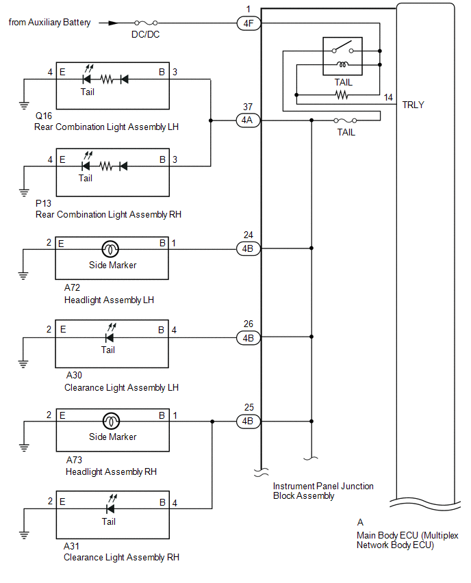
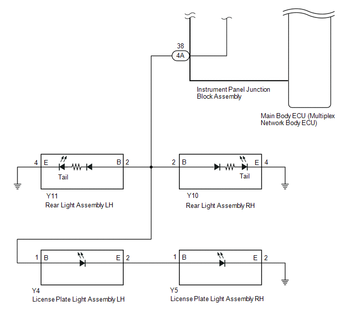
Illumination of the taillights and license plate light is controlled by the main body ECU (multiplex network body ECU).
WIRING DIAGRAM
CAUTION / NOTICE / HINT
NOTICE:
- Inspect the fuses for circuits related to this system before performing the following procedure.
- Recognition code registration is necessary when replacing the main body ECU (multiplex network body ECU).
-
If the main body ECU (multiplex network body ECU) is replaced, refer to Registration.
Click here
.gif)
PROCEDURE
| 1. | PERFORM ACTIVE TEST USING TECHSTREAM (TAILLIGHT RELAY) |
(a) Using the Techstream, perform the Active Test.
Click here
| Tester Display | Measurement Item | Control Range | Diagnostic Note |
|---|---|---|---|
| Taillight Relay | Taillight relay | ON or OFF | - |
| Tester Display |
|---|
| Taillight Relay |
| Result | Proceed to |
|---|---|
| Taillights, license lights and side marker lights come on | A |
| Taillights, license lights and side marker lights do not come on | B |
| A | .gif) | PROCEED TO NEXT SUSPECTED AREA SHOWN IN PROBLEM SYMPTOMS TABLE |
|
.gif)
| 2. | CHECK HARNESS AND CONNECTOR (INSTRUMENT PANEL JUNCTION BLOCK ASSEMBLY - BATTERY) |
(a) Disconnect the instrument panel junction block assembly connector.
| (b) Measure the voltage according to the value(s) in the table below. Standard Voltage:
|
|
.png)
| NG | | REPAIR OR REPLACE HARNESS OR CONNECTOR |
|
| 3. | INSPECT INSTRUMENT PANEL JUNCTION BLOCK ASSEMBLY |
(a) Remove the instrument panel junction block assembly.
Click here
(b) Remove the instrument panel junction block assembly.
Click here
(c) Measure the voltage according to the value(s) in the table below.
Standard Voltage:
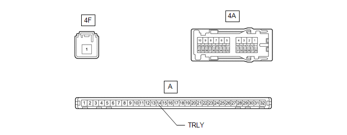
| Tester Connection | Condition | Specified Condition |
|---|---|---|
| 4A-37 - Battery negative (-) terminal | Battery voltage applied between terminals 4F-1 and A-14 (TRLY) | 11 to 14 V |
| Battery voltage not applied between terminals 4F-1 and A-14 (TRLY) | Below 1 V | |
| 4A-38 - Battery negative (-) terminal | Battery voltage applied between terminals 4F-1 and A-14 (TRLY) | 11 to 14 V |
| Battery voltage not applied between terminals 4F-1 and A-14 (TRLY) | Below 1 V | |
| 4B-24 - Battery negative (-) terminal | Battery voltage applied between terminals 4F-1 and A-14 (TRLY) | 11 to 14 V |
| Battery voltage not applied between terminals 4F-1 and A-14 (TRLY) | Below 1 V | |
| 4B-25 - Battery negative (-) terminal | Battery voltage applied between terminals 4F-1 and A-14 (TRLY) | 11 to 14 V |
| Battery voltage not applied between terminals 4F-1 and A-14 (TRLY) | Below 1 V | |
| 4B-25 - Battery negative (-) terminal | Battery voltage applied between terminals 4F-1 and A-14 (TRLY) | 11 to 14 V |
| Battery voltage not applied between terminals 4F-1 and A-14 (TRLY) | Below 1 V |
| OK | | REPLACE MAIN BODY ECU (MULTIPLEX NETWORK BODY ECU) |
| NG | | REPLACE INSTRUMENT PANEL JUNCTION BLOCK ASSEMBLY |
READ NEXT:
 Power Source Circuit
DESCRIPTION The main body ECU (multiplex network body ECU) receives IG signals and supplies power to the headlight ECU sub-assembly via the H-LP relay. WIRING DIAGRAM CAUTION / NOTICE / HINT NOTICE:
Cornering Light Circuit
DESCRIPTION The illumination of the fog light assembly (cornering light) is controlled by the headlight ECU sub-assembly. WIRING DIAGRAM CAUTION / NOTICE / HINT NOTICE:
The light system (for Tripl
SEE MORE:
Components
COMPONENTS ILLUSTRATION *1 ACCELERATION SENSOR *2 COWL SIDE TRIM BOARD LH *3 DOOR SCUFF PLATE ASSEMBLY LH *4 GLOVE COMPARTMENT DOOR ASSEMBLY *5 NO. 1 INSTRUMENT PANEL UNDER COVER SUB-ASSEMBLY *6 CONNECTOR N*m (kgf*cm, ft.*lbf): Specified torque - -
Dtc Check / Clear
DTC CHECK / CLEAR CHECK DTC (a) Connect the Techstream to the DLC3. (b) Turn the power switch on (IG). (c) Turn the intelligent clearance sonar system on. (d) Turn the Techstream on. (e) Enter the following menus: Body Electrical / Advanced Parking Guidance/ICS/Intuitive P/A / Trouble Codes. (f) Che
