Lexus NX: Power Source Circuit
DESCRIPTION
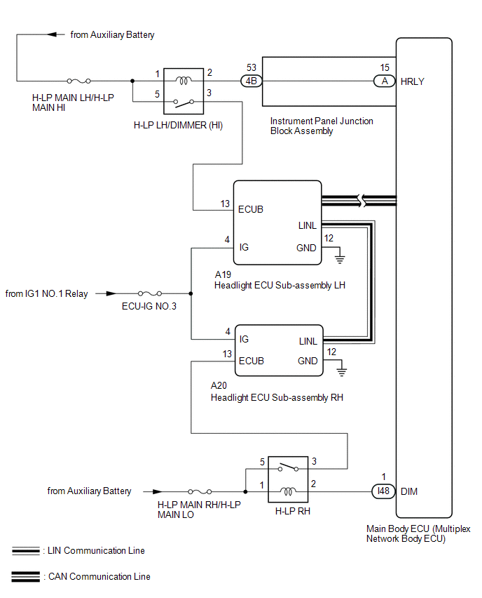
The main body ECU (multiplex network body ECU) receives IG signals and supplies power to the headlight ECU sub-assembly via the H-LP relay.
WIRING DIAGRAM
CAUTION / NOTICE / HINT
NOTICE:
-
The lighting system (for Triple Beam Headlight) uses the LIN communication system and CAN communication system. First, confirm that there are no malfunctions in the LIN communication system and CAN communication system. Refer to the How to Proceed with Troubleshooting procedure.
CAN communication system:
Click here
.gif)
LIN communication system:
Click here
- Inspect the fuses for circuits related to this system before performing the following inspection procedure.
- Recognition code registration is necessary when replacing the main body ECU (multiplex network body ECU).
-
If the main body ECU (multiplex network body ECU) is replaced, refer to Registration.
Click here
PROCEDURE
| 1. | CHECK HARNESS AND CONNECTOR (HEADLIGHT ECU SUB-ASSEMBLY - BATTERY AND BODY GROUND) |
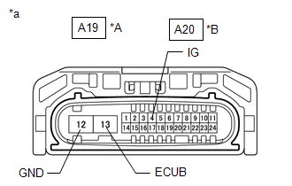
| (a) Disconnect the A19 headlight ECU sub-assembly LH or A20 headlight ECU sub-assembly RH connector. |
|
(b) Measure the voltage according to the value(s) in the table below.
Standard Voltage:
Headlight ECU Sub-assembly LH| Tester Connection | Switch Condition | Specified Condition |
|---|---|---|
| A19-13 (ECUB) - Body ground | Power switch on (IG) | 11 to 14 V |
| A19-4 (IG) - Body ground | Power switch on (IG) | 11 to 14 V |
| Tester Connection | Switch Condition | Specified Condition |
|---|---|---|
| A20-13 (ECUB) - Body ground | Power switch on (IG) | 11 to 14 V |
| A20-4 (IG) - Body ground | Power switch on (IG) | 11 to 14 V |
(c) Measure the resistance according to the value(s) in the table below.
Standard Resistance:
Headlight ECU Sub-assembly LH| Tester Connection | Condition | Specified Condition |
|---|---|---|
| A19-12 (GND) - Body ground | Always | Below 1 Ω |
| Tester Connection | Condition | Specified Condition |
|---|---|---|
| A20-12 (GND) - Body ground | Always | Below 1 Ω |
| Result | Proceed to |
|---|---|
| OK | A |
| NG (Headlight ECU Sub-assembly LH) | B |
| NG (Headlight ECU Sub-assembly RH) | C |
| A | .gif) | PROCEED TO NEXT SUSPECTED AREA SHOWN IN PROBLEM SYMPTOMS TABLE |
| C | | GO TO STEP 7 |
|
.gif)
| 2. | INSPECT HEADLIGHT DIMMER RELAY (H-LP LH/DIMMER [HI]) |
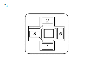
(a) Remove the headlight light dimmer relay (H-LP LH/DIMMER [HI]) from the engine room relay block.
(b) Inspect the headlight light dimmer relay (H-LP LH/DIMMER [HI]).
Click here
| NG | | REPLACE HEADLIGHT DIMMER RELAY (H-LP LH/DIMMER [HI]) |
|
| 3. | CHECK HARNESS AND CONNECTOR (HEADLIGHT DIMMER RELAY [H-LP LH/DIMMER (HI)] - BATTERY) |
| (a) Remove the headlight light dimmer relay (H-LP LH/DIMMER [HI]) from the engine room relay block. |
|
(b) Measure the voltage according to the value(s) in the table below.
Standard Voltage:
| Tester Connection | Switch Condition | Specified Condition |
|---|---|---|
| Relay terminal 1 - Body ground | Power switch off | 11 to 14 V |
| Relay terminal 5 - Body ground | Power switch off | 11 to 14 V |
| NG | | REPAIR OR REPLACE HARNESS OR CONNECTOR |
|
| 4. | CHECK HARNESS AND CONNECTOR (HEADLIGHT DIMMER RELAY [H-LP LH/DIMMER (HI)] - HEADLIGHT ECU SUB-ASSEMBLY LH) |
(a) Remove the headlight light dimmer relay (H-LP LH/DIMMER [HI]) from the engine room relay block.
(b) Disconnect the A19 headlight ECU sub-assembly LH connector.
(c) Measure the resistance according to the value(s) in the table below.
Standard Resistance:
| Tester Connection | Condition | Specified Condition |
|---|---|---|
| Relay terminal 3 - A19-13 (ECUB) | Always | Below 1 Ω |
| Relay terminal 3 or A19-13 (ECUB) - Body ground | Always | 10 kΩ or higher |
| NG | | REPAIR OR REPLACE HARNESS OR CONNECTOR |
|
| 5. | CHECK HARNESS AND CONNECTOR (HEADLIGHT DIMMER RELAY [H-LP LH/DIMMER (HI)] - MAIN BODY ECU [MULTIPLEX NETWORK BODY ECU]) |
(a) Remove the headlight light dimmer relay (H-LP LH/DIMMER [HI]) from the engine room relay block.
(b) Remove the instrument panel junction block assembly.
Click here
(c) Remove the main body ECU (multiplex network body ECU) from the instrument panel junction block assembly.
Click here
(d) Disconnect the 4B instrument panel junction block assembly connector.
(e) Measure the resistance according to the value(s) in the table below.
Standard Resistance:
| Tester Connection | Condition | Specified Condition |
|---|---|---|
| Relay terminal 2 - A-15 (HRLY) | Always | Below 1 Ω |
| Relay terminal 2 or A-15 (HRLY) - Body ground | Always | 10 kΩ or higher |
| OK | | REPLACE MAIN BODY ECU (MULTIPLEX NETWORK BODY ECU) |
|
| 6. | CHECK HARNESS AND CONNECTOR (HEADLIGHT DIMMER RELAY [H-LP LH/DIMMER (HI)] - INSTRUMENT PANEL JUNCTION BLOCK ASSEMBLY) |
(a) Remove the headlight light dimmer relay (H-LP LH/DIMMER [HI]) from the engine room relay block.
(b) Disconnect the 4B instrument panel junction block assembly connector.
(c) Measure the resistance according to the value(s) in the table below.
Standard Resistance:
| Tester Connection | Condition | Specified Condition |
|---|---|---|
| Relay terminal 2 - 4B-53 | Always | Below 1 Ω |
| Relay terminal 2 or 4B-53 - Body ground | Always | 10 kΩ or higher |
| OK | | REPLACE INSTRUMENT PANEL JUNCTION BLOCK ASSEMBLY |
| NG | | REPAIR OR REPLACE HARNESS OR CONNECTOR |
| 7. | CHECK HEADLIGHT RELAY (H-LP RH) |
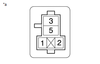
(a) Remove the headlight relay (H-LP RH) from the No. 2 engine room relay block.
(b) Inspect the headlight light relay (H-LP RH).
Click here
| NG | | REPLACE HEADLIGHT RELAY (H-LP RH RELAY) |
|
| 8. | CHECK HARNESS AND CONNECTOR (HEADLIGHT RELAY [H-LP RH] - BATTERY) |
| (a) Remove the headlight relay (H-LP RH) from the No. 2 engine room relay block. |
|
(b) Measure the voltage according to the value(s) in the table below.
Standard Voltage:
| Tester Connection | Switch Condition | Specified Condition |
|---|---|---|
| Relay terminal 1 - Body ground | Power switch off | 11 to 14 V |
| Relay terminal 5 - Body ground | Power switch off | 11 to 14 V |
| NG | | REPAIR OR REPLACE HARNESS OR CONNECTOR |
|
| 9. | CHECK HARNESS AND CONNECTOR (HEADLIGHT RELAY [H-LP RH RELAY] - HEADLIGHT ECU SUB-ASSEMBLY RH AND MAIN BODY ECU [MULTIPLEX NETWORK BODY ECU]) |
(a) Remove the headlight relay (H-LP RH) from the No. 2 engine room relay block.
(b) Disconnect the A20 headlight ECU sub-assembly RH connector.
(c) Disconnect the I48 main body ECU (multiplex network body ECU) connector.
(d) Measure the resistance according to the value(s) in the table below.
Standard Resistance:
| Tester Connection | Condition | Specified Condition |
|---|---|---|
| Relay terminal 3 - A20-13 (ECUB) | Always | Below 1 Ω |
| Relay terminal 2 - I48-1 (DIM) | Always | Below 1 Ω |
| Relay terminal 3 or A20-13 (ECUB) - Body ground | Always | 10 kΩ or higher |
| Relay terminal 2 or I48-1 (DIM) - Body ground | Always | 10 kΩ or higher |
| OK | | REPLACE MAIN BODY ECU (MULTIPLEX NETWORK BODY ECU) |
| NG | | REPAIR OR REPLACE HARNESS OR CONNECTOR |
READ NEXT:
 Cornering Light Circuit
DESCRIPTION The illumination of the fog light assembly (cornering light) is controlled by the headlight ECU sub-assembly. WIRING DIAGRAM CAUTION / NOTICE / HINT NOTICE:
The light system (for Tripl
Precaution
PRECAUTION NOTICE: When disassembling the rear combination light assembly, use static electricity countermeasures SST (desktop antistatic mat set) and observe all precautions to prevent damage to the
SEE MORE:
Reassembly
REASSEMBLY CAUTION / NOTICE / HINT HINT:
Use the same procedure for the RH and LH sides.
The procedure listed below is for the LH side.
PROCEDURE 1. INSTALL NO. 2 MOULDING TAPE (a) When using a new rear door rear upper outside moulding LH: (1) Clean the surface of a new rear door rear upper
Lost Communication with "Door Control Module A" (U0199)
DESCRIPTION DTC No. Detection Item DTC Detection Condition Trouble Area DTC Output from U0199 Lost Communication with "Door Control Module A" There is no communication from the outer mirror control ECU assembly LH.
Power source circuit of outer mirror control ECU assembly LH
