Lexus NX: Front Left Seat Heat Sensor Circuit (B14C1)
DESCRIPTION
Output to the front seat cushion heater temperature sensor stops if one of the following occurs: 1) the temperature sensor is open or shorted; or 2) the temperature sensor is damaged and its output value does not change.
| DTC No. | Detection Item | DTC Detection Condition | Trouble Area |
|---|---|---|---|
| B14C1 | Front Left Seat Heat Sensor Circuit | Seat heater temperature sensor malfunction |
|
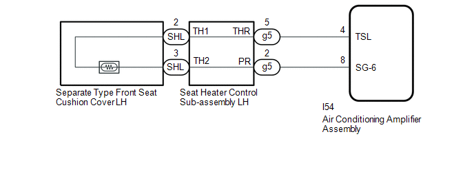
WIRING DIAGRAM
CAUTION / NOTICE / HINT
NOTICE:
-
If the auxiliary battery voltage is low, the seat heater system may not operate. When "High Power Consumption Partial Limit On AC/Heater Operation." is displayed on the multi-information display in the combination meter assembly, inspect the auxiliary battery, referring to On-vehicle Inspection for the charging system.
Click here
.gif)
HINT:
If the auxiliary battery voltage is low, "Operation Limitation Control History Count (Level 1)" and "Operation Limitation Control History Count (Level 2) is counted.
Click here
-
If the auxiliary battery voltage is low, the seat heater system may not operate. Refer to Data List for the power steering system.
for Manual Tilt and Manual Telescopic Steering Column: Click here
for Power Tilt and Power Telescopic Steering Column: Click here
PROCEDURE
| 1. | CLEAR DTC |
(a) Clear the DTCs.
Click here
|
.gif)
| 2. | CHECK FOR DTC |
(a) Check for DTCs.
Click here
OK:
DTC B14C1 is not output.
| OK | .gif) | USE SIMULATION METHOD TO CHECK |
|
| 3. | READ VALUE USING TECHSTREAM (FL Seat Heater Temperature) |
(a) Connect the Techstream to the DLC3.
(b) Turn the power switch on (IG).
(c) Turn the Techstream on.
(d) Enter the following menus: Body Electrical / Air Conditioner / Data List.
(e) Read the Data List according to the display on the Techstream.
Body Electrical > Air Conditioner > Data List| Tester Display | Measurement Item | Range | Normal Condition | Diagnostic Note |
|---|---|---|---|---|
| FL Seat Heater Temperature | Front seat LH heater temperature | -29.7°C to 59.55°C | Within range from 32 to 43°C (89 to 109°F) | Front seat heater is on |
| Tester Display |
|---|
| FL Seat Heater Temperature |
OK:
On the Techstream screen, the seat heater temperature is as specified in the normal condition column.
| OK | | REPLACE AIR CONDITIONING AMPLIFIER ASSEMBLY |
|
| 4. | INSPECT SEPARATE TYPE FRONT SEAT CUSHION COVER LH |
(a) Remove the separate type front seat cushion cover LH.
Click here
(b) Inspect the separate type front seat cushion cover LH.
Click here
| NG | | REPLACE SEPARATE TYPE FRONT SEAT CUSHION COVER LH |
|
| 5. | INSPECT SEAT HEATER CONTROL SUB-ASSEMBLY LH |
| (a) Disconnect the g5 and SHL seat heater control sub-assembly LH connectors. |
|
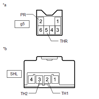
(b) Measure the resistance according to the value(s) in the table below.
Standard Resistance:
| Tester Connection | Condition | Specified Condition |
|---|---|---|
| g5-5 (THR) - SHL-2 (TH1) | Always | Below 1 Ω |
| g5-5 (THR) or SHL-2 (TH1) - Body ground | Always | 10 kΩ or higher |
| g5-2 (PR) - SHL-3 (TH2) | Always | Below 1 Ω |
| g5-2 (PR) or SHL-3 (TH2) - Body ground | Always | 10 kΩ or higher |
| NG | | REPLACE SEAT HEATER CONTROL SUB-ASSEMBLY LH |
|
| 6. | CHECK HARNESS AND CONNECTOR (AIR CONDITIONING AMPLIFIER ASSEMBLY - SEAT HEATER CONTROL SUB-ASSEMBLY LH) |
(a) Disconnect the I54 air conditioning amplifier assembly connector.
(b) Disconnect the g5 seat heater control sub-assembly LH connector.
(c) Measure the resistance according to the value(s) in the table below.
Standard Resistance:
| Tester Connection | Condition | Specified Condition |
|---|---|---|
| I54-4 (TSL) - g5-5 (THR) | Always | Below 1 Ω |
| I54-4 (TSL) or g5-5 (THR) - Body ground | Always | 10 kΩ or higher |
| I54-8 (SG-6) - g5-2 (PR) | Always | Below 1 Ω |
| I54-8 (SG-6) or g5-2 (PR) - Body ground | Always | 10 kΩ or higher |
| OK | | REPLACE AIR CONDITIONING AMPLIFIER ASSEMBLY |
| NG | | REPAIR OR REPLACE HARNESS OR CONNECTOR |
READ NEXT:
 Rear Right Seat Heat Sensor Circuit (B14C2)
DESCRIPTION Power supply to the temperature sensor built into the rear seat cushion heater stops if one of the following occurs: 1) an open or short occurs in the temperature sensor circuit; or 2) the
Rear Left Seat Heat Sensor Circuit (B14C3)
DESCRIPTION Power supply to the temperature sensor built into the rear seat cushion heater stops if one of the following occurs: 1) an open or short occurs in the temperature sensor circuit; or 2) the
Seat Heater Switch Circuit
DESCRIPTION When the refreshing seat switch is operated, the air conditioning amplifier assembly receives the signal via the LIN communication line, and operates the seat heater for the corresponding
SEE MORE:
Throttle Actuator Control Motor Circuit Low (P2102,P2103)
DESCRIPTION The throttle actuator is operated by the ECM and opens and closes the throttle valve using gears. The opening angle of the throttle valve is detected by the throttle position sensor, which is mounted on the throttle body with motor assembly. The throttle position sensor provides feedback
Diagnostic Trouble Code Chart
DIAGNOSTIC TROUBLE CODE CHART Air Conditioning System DTC No. Detection Item Memory Link B1411 Room Temperature Sensor Circuit Memorized (4 seconds or more) B1412 Ambient Temperature Sensor Circuit Memorized (4 seconds or more) B1413 Evaporator Temperature Ci
