Lexus NX: Rear Left Seat Heat Sensor Circuit (B14C3)
DESCRIPTION
Power supply to the temperature sensor built into the rear seat cushion heater stops if one of the following occurs: 1) an open or short occurs in the temperature sensor circuit; or 2) the temperature sensor is damaged and its output value does not change.
| DTC No. | Detection Item | DTC Detection Condition | Trouble Area |
|---|---|---|---|
| B14C3 | Rear Left Seat Heat Sensor Circuit | Seat heater temperature sensor malfunction |
|
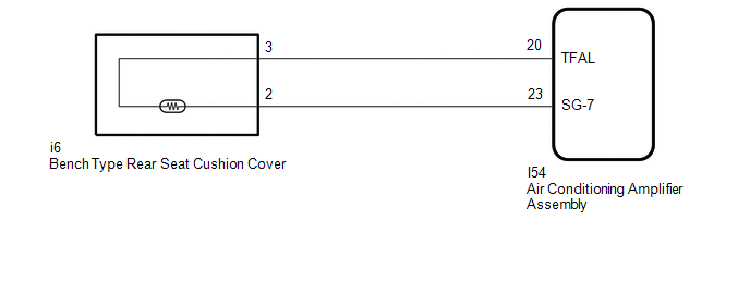
WIRING DIAGRAM
CAUTION / NOTICE / HINT
NOTICE:
-
If the auxiliary battery voltage is low, the seat heater system may not operate. When "High Power Consumption / Partial Limit On AC/Heater Operation" is displayed on the multi-information display in the combination meter assembly, inspect the auxiliary battery, referring to On-vehicle Inspection for the charging system.
HINT:
If the auxiliary battery voltage is low, "Operation Limitation Control History Count (Level 1)" and "Operation Limitation Control History Count (Level 2) is counted.
Click here
.gif)
Click here
-
If the auxiliary battery voltage is low, the seat heater system may not operate. Refer to Data List for the power steering system.
-
for Manual Tilt and Manual Telescopic Steering Column:
-
for Power Tilt and Power Telescopic Steering Column:
-
for Manual Tilt and Manual Telescopic Steering Column:
-
When the auxiliary battery is disconnected or the air conditioning amplifier assembly is replaced, be sure to perform servo motor initialization.
Click here
PROCEDURE
| 1. | CLEAR DTC |
(a) Clear the DTCs.
Click here
|
.gif)
| 2. | CHECK FOR DTC |
(a) Check for DTCs.
Click here
OK:
DTC B14C3 is not output.
| OK | .gif) | USE SIMULATION METHOD TO CHECK |
|
| 3. | READ VALUE USING TECHSTREAM (RL SEAT HEATER TEMPERATURE) |
(a) Connect the Techstream to the DLC3.
(b) Turn the power switch on (IG).
(c) Turn the Techstream on.
(d) Enter the following menus: Body Electrical / Air Conditioner / Data List.
(e) Read the Data List according to the display on the Techstream.
Body Electrical > Air Conditioner > Data List| Tester Display | Measurement Item | Range | Normal Condition | Diagnostic Note |
|---|---|---|---|---|
| RL Seat Heater Temperature | Rear seat LH heater temperature | -29.7°C to 59.55°C |
| Refreshing seat switch (for Rear seat LH) is on (w/ Rear Seat Heater) |
| Tester Display |
|---|
| RL Seat Heater Temperature |
OK:
On the Techstream screen, the seat heater temperature is as specified in the normal condition column.
| OK | | REPLACE AIR CONDITIONING AMPLIFIER ASSEMBLY |
|
| 4. | INSPECT BENCH TYPE REAR SEAT CUSHION COVER |
(a) Remove the bench type rear seat cushion cover.
-
for Manual Seat:
-
for Power Seat:
(b) Inspect the bench type rear seat cushion cover.
-
for Manual Seat:
-
for Power Seat:
| NG | | REPLACE BENCH TYPE REAR SEAT CUSHION COVER |
|
| 5. | CHECK HARNESS AND CONNECTOR (AIR CONDITIONING AMPLIFIER ASSEMBLY - BENCH TYPE REAR SEAT CUSHION COVER) |
(a) Disconnect the I54 air conditioning amplifier assembly connector.
(b) Disconnect the h6 bench type rear seat cushion cover connector.
(c) Measure the resistance according to the value(s) in the table below.
Standard Resistance:
| Tester Connection | Condition | Specified Condition |
|---|---|---|
| I54-20 (TFAL) - i6-3 | Always | Below 1 Ω |
| I54-20 (TFAL) or i6-3 - Body ground | Always | 10 kΩ or higher |
| I54-23 (SG-7) - i6-2 | Always | Below 1 Ω |
| I54-23 (SG-7) or i6-2 - Body ground | Always | 10 kΩ or higher |
| OK | | REPLACE AIR CONDITIONING AMPLIFIER ASSEMBLY |
| NG | | REPAIR OR REPLACE HARNESS OR CONNECTOR |
READ NEXT:
 Seat Heater Switch Circuit
DESCRIPTION When the refreshing seat switch is operated, the air conditioning amplifier assembly receives the signal via the LIN communication line, and operates the seat heater for the corresponding
Seat Heater for Front Right Seat does not Operate
DESCRIPTION When the seat heater switch on air conditioning control assembly is operated, the air conditioning amplifier assembly receives the signal. The air conditioning amplifier assembly receives
Seat Heater for Front Left Seat does not Operate
DESCRIPTION When the seat heater switch on air conditioning control assembly is operated, the air conditioning amplifier assembly receives the signal. The air conditioning amplifier assembly receives
SEE MORE:
Problem Symptoms Table
PROBLEM SYMPTOMS TABLE NOTICE: When replacing the combination meter assembly, always replace it with a new one. If a combination meter assembly which was installed to another vehicle is used, the information stored in it will not match the information from the vehicle and a DTC may be stored. HINT:
Automatic High Beam
The Automatic High Beam uses an
in-vehicle camera sensor to assess
the brightness of streetlights, the
lights of oncoming and preceding
vehicles, etc., and automatically
turns high beam on or off as necessary.
WARNING
■Limitations of the Automatic High
Beam
Do not rely on the Automatic Hi
