Lexus NX: Removal
REMOVAL
CAUTION / NOTICE / HINT
HINT:
- Use the same procedure for the RH and LH sides.
- The procedure listed below is for the LH side.
-
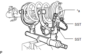
SST used when removing/installing the coil spring are shown as follows.
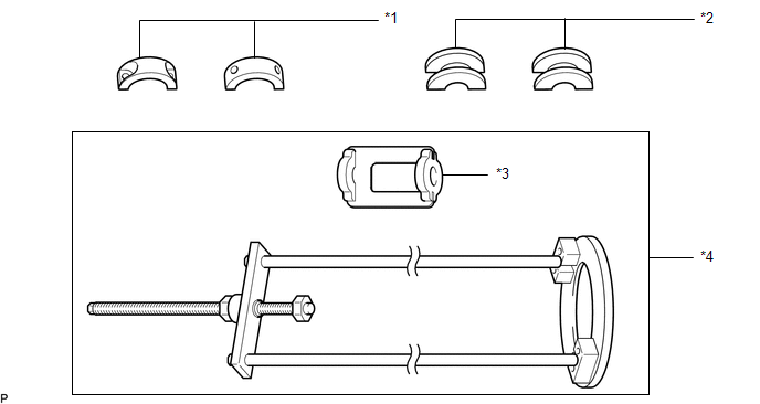
*1
SST(09727-58100)
*2
SST(09727-58130)
*3
SST(09727-58030)
*4
SST(09727-58010)
PROCEDURE
1. REMOVE OUTER COWL TOP PANEL
Click here .gif)
2. REMOVE FRONT WHEEL
Click here
3. DISCONNECT FRONT SPEED SENSOR LH (w/ AVS)
Click here
4. DISCONNECT FRONT SPEED SENSOR LH (w/o AVS)
Click here
5. DISCONNECT FRONT SKID CONTROL SENSOR WIRE LH (w/ AVS)
Click here
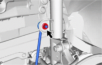
6. DISCONNECT FRONT STABILIZER LINK ASSEMBLY LH
| (a) Remove the nut and disconnect the stabilizer link assembly from the front shock absorber with coil spring. HINT: If the ball joint turns together with the nut, use a 6 mm hexagon wrench to hold the stud bolt. |
|
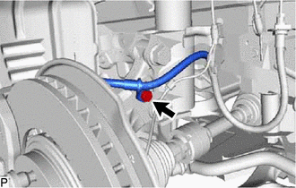
7. DISCONNECT FRONT FLEXIBLE HOSE (w/o AVS)
| (a) Remove the bolt and disconnect the front flexible hose. |
|
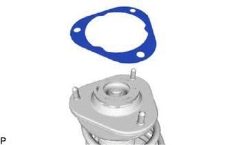
8. REMOVE FRONT SUSPENSION SUPPORT DUST COVER LH
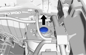
(a) Remove the front suspension support dust cover LH.
9. REMOVE FRONT SHOCK ABSORBER WITH COIL SPRING
| (a) Support the front lower arm using a jack and wooden block. |
|
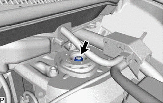
| (b) Loosen the front support to front shock absorber nut of the front shock absorber. NOTICE:
|
|
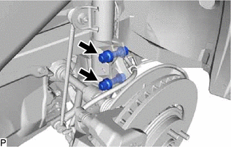
| (c) Remove the 2 bolts and 2 nuts and disconnect the front shock absorber with coil spring from the steering knuckle. |
|
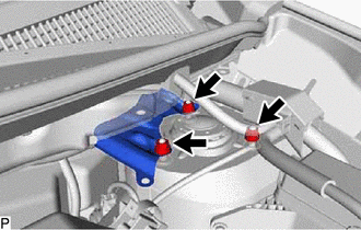
| (d) Remove the 3 nuts, cowl body mounting reinforcement LH and front shock absorber with coil spring. |
|
10. REMOVE FRONT SUSPENSION SUPPORT PLATE LH
| (a) Remove the front suspension support plate from the front shock absorber with coil spring. |
|
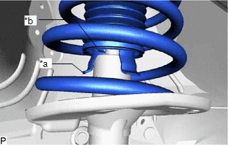
11. DISCONNECT FRONT SPRING SEAT SUB-ASSEMBLY WITH INSULATOR LH
| (a) Disconnect the end of the insulator of the front spring seat sub-assembly with insulator LH from the claws of the front shock absorber LH. |
|
12. REMOVE FRONT SUPPORT TO FRONT SHOCK ABSORBER NUT
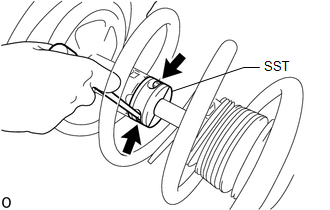
| (a) Using a piece of cloth, etc., clean the shock rod and remove any foreign matter and oil. NOTICE: Thoroughly clean the shock rod to prevent damage to the shock rod due to contact of foreign matter. |
|
| (b) Attach SST (09727-58130) to SST (09727-58100). SST: 09727-58100 SST: 09727-58130 NOTICE: Check that there are no cracks or damage in SST (09727-58130) that could prevent it from securing the shock rod of the front shock absorber assembly LH. If there are, replace SST (09727-58130) with a new one. |
|
| (c) Clean the surface of SST (09727-58130) to which the front shock absorber assembly LH is installed and remove any foreign matter and oil. NOTICE: Thoroughly clean the installation surface to prevent damage to the shock rod due to contact of foreign matter. |
|
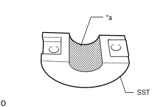
| (d) Using a long ball hexagon 5, install SST (09727-58100) and SST (09727-58130) to the shock rod. NOTICE: When installing SST (09727-58100) and SST (09727-58130), do not fold back the No. 1 front shock absorber dust cover LH in an improper direction and deform it. HINT:
|
|
(e) For SST with stopper pins:
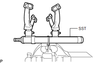
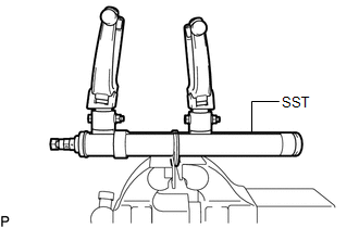
(1) Secure SST in a vise.
SST: 09727-30022
09727-00010
09727-00022
09727-00031
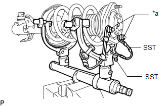
| (2) Attach the hooks of each SST arm across the diameter of the coil spring. CAUTION:
|
|
| (3) Install the stopper pins to the hooks of SST. CAUTION: Make sure that the stopper pins are installed securely. |
|
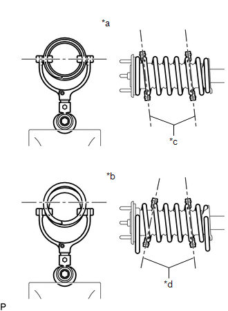
| (4) Install SST and 2 vehicle nuts to the upper support as shown in the illustration. SST: 09727-30022 09727-00090 09727-00100 |
|
(5) Using SST, compress the coil spring.
CAUTION:
- If the coil spring bends while using SST, stop immediately and reattach SST correctly.
- Do not compress the coil spring to the point where the coils touch each other.
- Do not use an impact wrench.
-
If a stopper pin touches the coil spring while using SST, remove the stopper pin and continue with the procedure. In this case, installing the coil spring stopper belt as shown in the illustration is recommended.
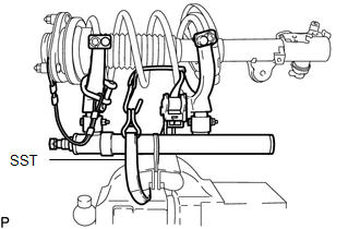
SST: 09727-00110
(6) Check that the coil spring has become detached, and then remove the front support to front shock absorber nut.
CAUTION:
Do not remove the front support to front shock absorber nut if the coil spring is not free.
(f) For SST without stopper pins:
| (1) Secure SST in a vise. SST: 09727-30021 09727-00010 09727-00021 09727-00031 |
|
| (2) Attach the hooks of each SST arm across the diameter of the coil spring. CAUTION:
|
|
| (3) Install SST and 2 vehicle nuts to the upper support as shown in the illustration. SST: 09727-30021 09727-00090 09727-00100 |
|
(4) Using SST, compress the coil spring.
CAUTION:
- If the coil spring bends while using SST, stop immediately and reattach SST correctly.
- Do not compress the coil spring to the point where the coils touch each other.
- Do not use an impact wrench.
HINT:
Installing SST as shown in the illustration is recommended.

SST: 09727-00110
(5) Check that the coil spring has become detached, and then remove the front support to front shock absorber nut.
CAUTION:
Do not remove the front support to front shock absorber nut if the coil spring is not free.
13. REMOVE COLLAR
14. REMOVE FRONT SUSPENSION SUPPORT SUB-ASSEMBLY LH
15. REMOVE FRONT SPRING SEAT SUB-ASSEMBLY WITH INSULATOR LH
16. REMOVE FRONT COIL SPRING LH
(a) Remove SST from the front coil spring.
NOTICE:
Do not use an impact wrench. It will damage SST.
17. REMOVE FRONT SPRING BUMPER LH
18. REMOVE FRONT COIL SPRING LOWER INSULATOR LH
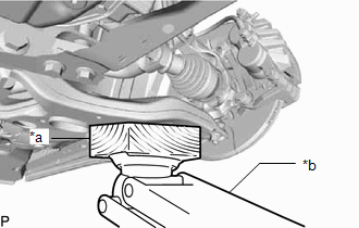
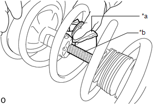
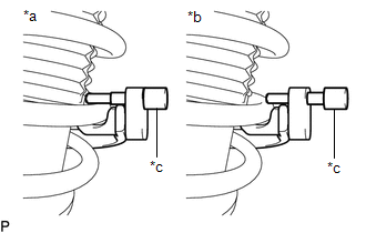
19. REMOVE FRONT SHOCK ABSORBER ASSEMBLY LH
(a) Using SST (09727-58010), remove SST (09727-58100) and SST (09727-58130) from the front shock absorber assembly LH.
SST: 09727-58010
09727-58030
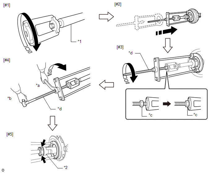
| *1 | Front Shock Absorber Assembly LH | *2 | Shock Absorber Outer Shell |
| *a | Turn | *b | Hold |
| *c | Fixing Nut | *d | Bolt |
NOTICE:
Apply molybdenum grease to the bolt (area with diagonal lines) of SST (09727-58010).
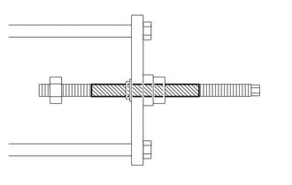
 | Application Area |
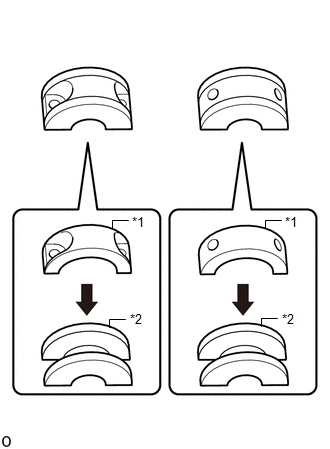
(1) Install SST (09727-58030) to the end of the shock rod of the front shock absorber assembly LH.[#1]
(2) Install SST (09727-58010) to the front shock absorber assembly LH.[#2]
NOTICE:
Take due care when installing SST (09727-58010) to ensure the shock rod is not damaged.
(3) Secure the SST (09727-58010) bolt and SST (09727-58030) with the fixing nut.[#3]
(4) After securing the SST (09727-58010) bolt, rotate the nut clockwise.[#4]
NOTICE:
Extend the shock rod until SST (09727-58100) and SST (09727-58130) separate from the shock absorber outer shell.
(5) Using a long ball hexagon 5, remove SST (09727-58100) and SST (09727-58130).[#5]
NOTICE:
If SST (09727-58100) and SST (09727-58130) are removed without using SST (09727-58010), the action of the rebound spring will cause the shock rod to contract suddenly. Therefore, remove SST (09727-58100) and SST (09727-58130) after securing the shock rod with SST (09727-58010).
(6) Using a piece of cloth, etc., clean the shock rod of the front shock absorber assembly LH and remove any foreign matter and oil.
NOTICE:
If the shock rod is expanded/contracted while foreign matter or oil are still present, it may damage the front shock absorber assembly LH or cause oil leaks.
(7) After securing the SST (09727-58010) bolt, rotate the nut counterclockwise.
(8) Check that the shock rod and SST (09727-58030) have become free before releasing the fixing nut and removing SST (09727-58010) from the shock rod.
NOTICE:
Take due care when removing SST (09727-58010) to ensure the shock rod is not damaged.
(9) Remove SST (09727-58030) from the end of the shock rod.
(10) Using a piece of cloth, etc., clean the end of the shock rod threads and remove any foreign matter and oil.
READ NEXT:
 Inspection
INSPECTION PROCEDURE 1. INSPECT FRONT SHOCK ABSORBER ASSEMBLY LH (a) Compress and extend the shock absorber rod 4 or more times and check the operating sound and resistance. Standard: The operating s
Installation
INSTALLATION CAUTION / NOTICE / HINT HINT:
Use the same procedure for the RH and LH sides.
The procedure listed below is for the LH side.
PROCEDURE 1. INSTALL SST (a) Align the cutout on end o
Disposal
DISPOSAL CAUTION / NOTICE / HINT HINT:
Use the same procedure for the RH and LH sides.
The procedure listed below is for the LH side.
PROCEDURE 1. DISPOSE OF FRONT SHOCK ABSORBER ASSEMBLY LH
SEE MORE:
VIN not Programmed or Mismatch - ECM / PCM (P0630)
MONITOR DESCRIPTION DTC P0630 is stored when the Vehicle Identification Number (VIN) is not stored in the ECM or the input VIN is not accurate. DTC No. Detection Item DTC Detection Condition Trouble Area MIL Memory P0630 VIN not Programmed or Mismatch - ECM / PCM Either of the f
Cold Start Ignition Timing Performance (P050B)
MONITOR DESCRIPTION This monitor will run when the engine is started at an engine coolant temperature of -10 to 50°C (14 to 122°F). The DTC is stored after the engine idles for 13 seconds (2 trip detection logic). The DTC is designed to monitor the ignition timing at cold start. When the engine is
