Lexus NX: Front Power Seat does not Operate with Front Power Seat Switch
DESCRIPTION
Signals are input into the front power seat switch LH. The built-in ECU manages the signals received from the power seat switch, and operates each motor. If the front power seat switch LH receives more than 2 motor operation signals, the motor is stopped. Manual operation is restarted after the front power seat switch LH receives 1 signal only.
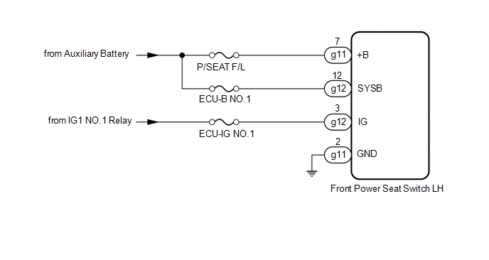
WIRING DIAGRAM
CAUTION / NOTICE / HINT
NOTICE:
Inspect the fuses for circuits related to this system before performing the following procedure.
PROCEDURE
| 1. | CHECK FRONT POWER SEAT OPERATION |
(a) Check that each function of the power seat operates normally by using the front power seat switch LH.
Click here .gif)
| Result | Proceed to |
|---|---|
| All power seat functions do not operate | A |
| One or more power seat functions do not operate | B |
| B | .gif) | GO TO OTHER DIAGNOSIS PROCEDURE (One or more Power Seat Motors do not Operate) |
|
.gif)
| 2. | CHECK HARNESS AND CONNECTOR (FRONT POWER SEAT SWITCH LH - BATTERY AND BODY GROUND) |
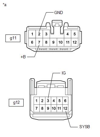
| (a) Disconnect the g11 and g12 front power seat switch LH connectors. |
|
(b) Measure the resistance according to the value(s) in the table below.
Standard Resistance:
| Tester Connection | Condition | Specified Condition |
|---|---|---|
| g11-2 (GND) - Body ground | Always | Below 1 Ω |
(c) Measure the voltage according to the value(s) in the table below.
Standard Voltage:
| Tester Connection | Switch Condition | Specified Condition |
|---|---|---|
| g11-7 (+B) - Body ground | Power switch off | 11 to 14 V |
| g12-3 (IG) - Body ground | Power switch on (IG) | 11 to 14 V |
| Power switch off | Below 1 V | |
| g12-12 (SYSB) - Body ground | Power switch off | 11 to 14 V |
| OK | | REPLACE FRONT POWER SEAT SWITCH LH |
| NG | | REPAIR OR REPLACE HARNESS OR CONNECTOR |
READ NEXT:
 One or more Power Seat Motors do not Operate
DESCRIPTION Signals are input into the front power seat switch LH. The built-in ECU manages the signals received from the front power seat switch LH, and operates each motor. If the front power seat s
Power Seat Position is not Memorized
DESCRIPTION The main body ECU (multiplex network body ECU) receives seat memory switch signals from the outer mirror control ECU assembly (for Driver Side) via CAN communication. If the seat memory SE
Power Seat does not Return to Memorized Position
DESCRIPTION When either the M1, M2 or M3 switch is pressed, the outer mirror control ECU assembly (for Driver Side) sends a switch signal to the main body ECU (multiplex network body ECU) via CAN comm
SEE MORE:
On-vehicle Inspection
ON-VEHICLE INSPECTION CAUTION / NOTICE / HINT CAUTION: Be sure to follow the correct removal and installation procedures of the front airbag sensors. PROCEDURE 1. INSPECT FRONT AIRBAG SENSOR (for Vehicle not Involved in Collision) (a) Perform a diagnostic system check. Click here 2. INSPECT FRONT
Steering Vibrator System Missing Message (C1A7587)
DESCRIPTION The forward recognition camera communicates with the steering vibration ECU via LIN communication. If a communication error between the forward recognition camera and steering vibration ECU is detected, DTC C1A7587 is stored. DTC No. Detection Item DTC Detection Condition Troubl
