Lexus NX: Front Right Seat Heat Sensor Circuit (B14C0)
DESCRIPTION
Output to the front seat cushion heater temperature sensor stops if one of the following occurs: 1) the temperature sensor is open or shorted; or 2) the temperature sensor is damaged and its output value does not change.
| DTC No. | Detection Item | DTC Detection Condition | Trouble Area |
|---|---|---|---|
| B14C0 | Front Right Seat Heat Sensor Circuit | Seat heater temperature sensor malfunction |
|
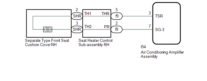
WIRING DIAGRAM
CAUTION / NOTICE / HINT
NOTICE:
-
If the auxiliary battery voltage is low, the seat heater system may not operate. When "High Power Consumption / Partial Limit On AC/Heater Operation" is displayed on the multi-information display in the combination meter assembly, inspect the auxiliary battery, referring to On-vehicle Inspection for the charging system.
Click here
.gif)
HINT:
If the auxiliary battery voltage is low, "Operation Limitation Control History Count (Level 1)" and "Operation Limitation Control History Count (Level 2) is counted.
Click here
-
If the auxiliary battery voltage is low, the seat heater system may not operate. Refer to Data List for the power steering system.
for Manual Tilt and Manual Telescopic Steering Column: Click here
Click here
PROCEDURE
| 1. | CLEAR DTC |
(a) Clear the DTCs.
Click here
|
.gif)
| 2. | CHECK FOR DTC |
(a) Check for DTCs.
Click here
OK:
DTC B14C0 is not output.
| OK | .gif) | USE SIMULATION METHOD TO CHECK |
|
| 3. | READ VALUE USING TECHSTREAM (FR Seat Heater Temperature) |
(a) Connect the Techstream to the DLC3.
(b) Turn the power switch on (IG).
(c) Turn the Techstream on.
(d) Enter the following menus: Body Electrical / Air Conditioner / Data List.
(e) Read the Data List according to the display on the Techstream.
Body Electrical > Air Conditioner > Data List| Tester Display | Measurement Item | Range | Normal Condition | Diagnostic Note |
|---|---|---|---|---|
| FR Seat Heater Temperature | Front seat RH heater temperature | -29.7°C to 59.55°C | Within range from 32 to 43°C (89 to 109°F) | Front seat heater is on |
| Tester Display |
|---|
| FR Seat Heater Temperature |
OK:
On the Techstream screen, the seat heater temperature is as specified in the normal condition column.
| OK | | REPLACE AIR CONDITIONING AMPLIFIER ASSEMBLY |
|
| 4. | INSPECT SEPARATE TYPE FRONT SEAT CUSHION COVER RH |
(a) Remove the separate type front seat cushion cover RH.
Click here
(b) Inspect the separate type front seat cushion cover RH.
Click here
| NG | | REPLACE SEPARATE TYPE FRONT SEAT CUSHION COVER RH |
|
| 5. | INSPECT SEAT HEATER CONTROL SUB-ASSEMBLY RH |
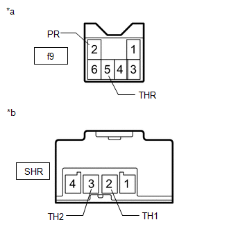
| (a) Disconnect the f9 and SHR seat heater control sub-assembly RH connectors. |
|
(b) Measure the resistance according to the value(s) in the table below.
Standard Resistance:
| Tester Connection | Condition | Specified Condition |
|---|---|---|
| f9-5 (THR) - SHR-2 (TH1) | Always | Below 1 Ω |
| f9-5 (THR) or SHR-2 (TH1) - Body ground | Always | 10 kΩ or higher |
| f9-2 (PR) - SHR-3 (TH2) | Always | Below 1 Ω |
| f9-2 (PR) or SHR-3 (TH2) - Body ground | Always | 10 kΩ or higher |
| NG | | REPLACE SEAT HEATER CONTROL SUB-ASSEMBLY RH |
|
| 6. | CHECK HARNESS AND CONNECTOR (AIR CONDITIONING AMPLIFIER ASSEMBLY - SEAT HEATER CONTROL SUB-ASSEMBLY RH) |
(a) Disconnect the I54 air conditioning amplifier assembly connector.
(b) Disconnect the f9 seat heater control sub-assembly RH connector.
(c) Measure the resistance according to the value(s) in the table below.
Standard Resistance:
| Tester Connection | Condition | Specified Condition |
|---|---|---|
| I54-3 (TSR) - f9-5 (THR) | Always | Below 1 Ω |
| I54-3 (TSR) or f9-5 (THR) - Body ground | Always | 10 kΩ or higher |
| I54-7 (SG-3) - f9-2 (PR) | Always | Below 1 Ω |
| I54-7 (SG-3) or f9-2 (PR) - Body ground | Always | 10 kΩ or higher |
| OK | | REPLACE AIR CONDITIONING AMPLIFIER ASSEMBLY |
| NG | | REPAIR OR REPLACE HARNESS OR CONNECTOR |
READ NEXT:
 Front Left Seat Heat Sensor Circuit (B14C1)
DESCRIPTION Output to the front seat cushion heater temperature sensor stops if one of the following occurs: 1) the temperature sensor is open or shorted; or 2) the temperature sensor is damaged and i
Rear Right Seat Heat Sensor Circuit (B14C2)
DESCRIPTION Power supply to the temperature sensor built into the rear seat cushion heater stops if one of the following occurs: 1) an open or short occurs in the temperature sensor circuit; or 2) the
Rear Left Seat Heat Sensor Circuit (B14C3)
DESCRIPTION Power supply to the temperature sensor built into the rear seat cushion heater stops if one of the following occurs: 1) an open or short occurs in the temperature sensor circuit; or 2) the
SEE MORE:
Back Door Closer Switch Malfunction (B2251)
DESCRIPTION The multiplex network door ECU receives signals from the latch switch, initial switch, pawl switch and back door courtesy switch, which are built into the back door lock assembly. Based on these switch signals, the latch position of the back door lock assembly is determined. DTC No.
Short in D Squib Circuit (B1800-B1803)
DESCRIPTION The driver side squib circuit consists of the airbag ECU assembly, spiral cable sub-assembly and horn button assembly. The circuit instructs the SRS to deploy when deployment conditions are met. These DTCs are stored when a malfunction is detected in the driver side squib circuit. DTC
