Lexus NX: Front Turn Signal Light Bulb(for Bulb Type Turn Signal Light)
Replacement
REPLACEMENT
CAUTION / NOTICE / HINT
HINT:
- Use the same procedure for the RH and LH sides.
- The procedure listed below is for the LH side.
PROCEDURE
1. REMOVE FRONT RADIATOR SIDE AIR GUIDE PLATE LH
| (a) Remove the clip. |
|
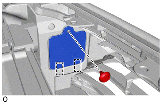
(b) Detach the 2 guides and remove the front radiator side air guide plate LH.
2. REMOVE FRONT TURN SIGNAL LIGHT BULB
(a) Turn the bulb socket counterclockwise until the matchmark is aligned with the unlock position mark to disconnect the bulb socket.
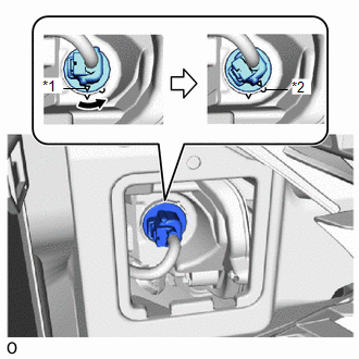
| *1 | Matchmark |
| *2 | Unlock Position Mark |
.png) | Counterclockwise |
| (b) Remove the front turn signal light bulb from the bulb socket. |
|
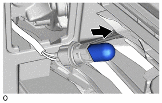
3. INSTALL FRONT TURN SIGNAL LIGHT BULB
(a) Install the front turn signal light bulb to the bulb socket.
(b) Align the matchmark of the bulb socket to the unlock position mark, and then rotate the bulb socket clockwise until the lock position mark to connect the bulb socket.
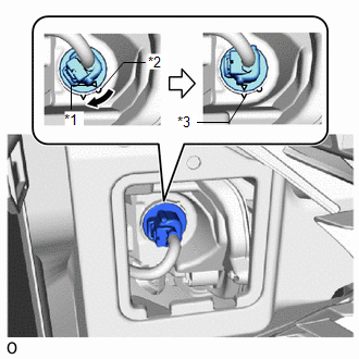
| *1 | Matchmark |
| *2 | Unlock Position Mark |
| *3 | Lock Position Mark |
| | Clockwise |
4. INSTALL FRONT RADIATOR SIDE AIR GUIDE PLATE LH
(a) Attach the 2 guides to install the front radiator side air guide plate LH.
(b) Install the clip.
5. INSPECT FRONT TURN SIGNAL LIGHT
Click here .gif)
READ NEXT:
 Hazard Warning Switch
InspectionINSPECTION PROCEDURE 1. INSPECT AIR CONDITIONING CONTROL ASSEMBLY (HAZARD WARNING SWITCH) (a) Remove the air conditioning control assembly. Click here (b) Inspect the hazard warning swit
Precaution
PRECAUTION NOTICE: When disassembling the headlight assembly, use static electricity countermeasures SST (desktop antistatic mat set) and observe all precautions to prevent damage to the system by ele
SEE MORE:
High Voltage Power Resource (P3004-803)
DTC SUMMARY MALFUNCTION DESCRIPTION The hybrid vehicle control ECU monitors the high-voltage wiring between the HV battery and inverter with converter assembly and detects an open circuit malfunction. HINT:
This DTC is differentiated from P3004-131 based on detection timing (after power switch is
Rear Window Defogger System does not Operate
DESCRIPTION When the rear window defogger switch on the air conditioning control assembly is pressed, the operation signal is transmitted to the air conditioning amplifier assembly via LIN communication. When the air conditioning amplifier assembly receives the signal, it turns on the defogger relay
