Lexus NX: Fuel Pressure Regulator
Components
COMPONENTS
ILLUSTRATION
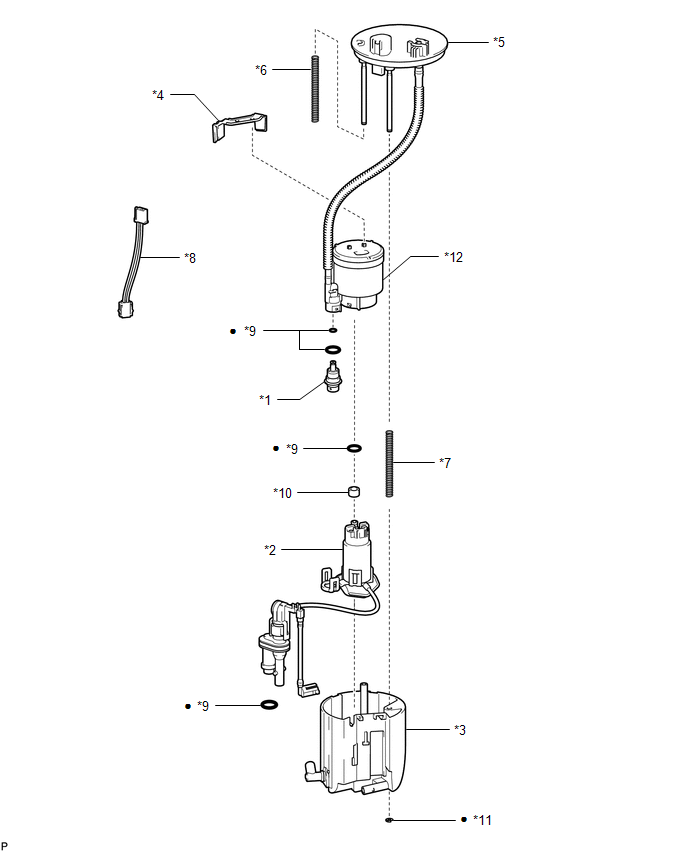
| *1 | FUEL PRESSURE REGULATOR ASSEMBLY | *2 | FUEL PUMP ASSEMBLY WITH FILTER |
| *3 | NO. 1 FUEL SUB-TANK | *4 | NO. 1 FUEL SUCTION SUPPORT |
| *5 | FUEL SUCTION PLATE SUB-ASSEMBLY | *6 | NO. 2 FUEL TANK CUSHION |
| *7 | NO. 3 FUEL TANK CUSHION | *8 | FUEL PUMP HARNESS |
| *9 | O-RING | *10 | FUEL PUMP SPACER |
| *11 | FUEL TANK PIPE SETTING HOLDER | *12 | FUEL FILTER ASSEMBLY |
| ● | Non-reusable part | - | - |
Removal
REMOVAL
CAUTION / NOTICE / HINT
NOTICE:
Do not try to remove the black nylon tube as it is welded to the fuel suction tube assembly.
Click here .gif)
PROCEDURE
1. REMOVE FUEL SUCTION TUBE ASSEMBLY WITH PUMP
Click here
2. REMOVE NO. 1 FUEL SUB-TANK
Click here
3. REMOVE NO. 1 FUEL SUCTION SUPPORT
Click here
4. REMOVE FUEL PUMP ASSEMBLY WITH FILTER
Click here
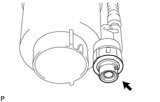
5. REMOVE FUEL PRESSURE REGULATOR ASSEMBLY
| (a) Using a screwdriver with its tip wrapped in protective tape, remove the fuel pressure regulator assembly. NOTICE: Slowly pull out the fuel pressure regulator assembly because the O-ring is firmly installed between the fuel pressure regulator assembly and fuel filter assembly. |
|
(b) Remove the 2 O-rings from the fuel pressure regulator assembly.
Installation
INSTALLATION
CAUTION / NOTICE / HINT
NOTICE:
Do not try to remove the black nylon tube as it is welded to the fuel suction tube assembly.
Click here .gif)
PROCEDURE
1. INSTALL FUEL PRESSURE REGULATOR ASSEMBLY
(a) Apply gasoline to 2 new O-rings and then install them to the fuel pressure regulator assembly.
(b) Install the fuel pressure regulator assembly.
2. INSTALL FUEL PUMP ASSEMBLY WITH FILTER
Click here
3. INSTALL NO. 1 FUEL SUCTION SUPPORT
Click here
4. INSTALL NO. 1 FUEL SUB-TANK
Click here
5. INSTALL FUEL SUCTION TUBE ASSEMBLY WITH PUMP
Click here
READ NEXT:
 Components
COMPONENTS ILLUSTRATION *1 FUEL SUCTION TUBE ASSEMBLY *2 FUEL TANK MAIN TUBE SUB-ASSEMBLY *3 FUEL TANK VENT TUBE SET PLATE *4 TUBE JOINT CLIP *5 FUEL HOSE *6 GASKET
Removal
REMOVAL PROCEDURE 1. REMOVE FUEL TANK ASSEMBLY Click here 2. DISCONNECT FUEL TANK MAIN TUBE SUB-ASSEMBLY (a) Remove the tube joint clip, then disconnect the fuel tank main tube sub-assembly from
SEE MORE:
Components
COMPONENTS ILLUSTRATION *1 FUEL SUCTION TUBE ASSEMBLY *2 FUEL TANK MAIN TUBE SUB-ASSEMBLY *3 FUEL TANK VENT TUBE SET PLATE *4 TUBE JOINT CLIP *5 FUEL HOSE *6 GASKET N*m (kgf*cm, ft.*lbf): Specified torque ● Non-reusable part ILLUSTRATION *1 FUEL PU
Installation
INSTALLATION PROCEDURE 1. INSTALL METER MIRROR SUB-ASSEMBLY (HEADUP DISPLAY) (a) Install the meter mirror sub-assembly (headup display) with the 4 screws. *a Screw *b Connector (b) Connect the connector. 2. INSTALL NO. 1 HEATER TO REGISTER DUCT SUB-ASSEMBLY (a) Insta
