Lexus NX: Generator Temperature Sensor Circuit Low (P0A38-257,P0A39-259)
DESCRIPTION
Refer to the description for DTC P0A37-260.
Click here .gif)
| DTC No. | Detection Item | DTC Detection Condition | Trouble Area | MIL | Warning Indicate |
|---|---|---|---|---|---|
| P0A38-257 | Generator Temperature Sensor Circuit Low | Short to ground in the generator temperature sensor circuit (1 trip detection logic) |
| Comes on | Master Warning Light: Comes on |
| P0A39-259 | Generator Temperature Sensor Circuit High | Open or short to +B in the generator temperature sensor circuit (1 trip detection logic) |
| Comes on | Master Warning Light: Comes on |
| DTC No. | Data List |
|---|---|
| P0A38-257 | Motor Temp No2 |
| P0A39-259 |
HINT:
After confirming that DTC P0A38-257 or P0A39-259 is output, use the Techstream to check "Motor Temp No2" in the Data List.
| Displayed Temperature | Malfunction |
|---|---|
| -40°C (-40°F) | Open circuit or short to +B |
| 215°C (419°F) | Short circuit or short to ground |
MONITOR DESCRIPTION
If the hybrid vehicle control ECU detects a malfunction of the generator temperature sensor, it will illuminate the MIL and store a DTC.
MONITOR STRATEGY
| Related DTCs | P0A38 (INF 257): Generator Temperature Sensor Circuit Low P0A39 (INF 259): Generator Temperature Sensor Circuit High |
| Required sensors / components | Generator temperature sensor |
| Frequency of operation | Continuous |
| Duration | TMC's intellectual property |
| MIL operation | 1 driving cycle |
| Sequence of operation | None |
TYPICAL ENABLING CONDITIONS
| The monitor will run whenever the following DTCs are not present | TMC's intellectual property |
| Other conditions belong to TMC's intellectual property | - |
TYPICAL MALFUNCTION THRESHOLDS
| TMC's intellectual property | - |
COMPONENT OPERATING RANGE
| Hybrid vehicle control ECU assembly | DTC P0A38 (INF 257) is not detected DTC P0A39 (INF 259) is not detected |
CONFIRMATION DRIVING PATTERN
HINT:
After the repair, clear the DTCs and perform the following procedure to check that DTCs are not output.
- Connect the Techstream to the DLC3.
- Turn the power switch on (IG) and turn the Techstream on.
- Clear the DTCs (even if no DTCs are stored, perform the clear DTC procedure).
- Turn the power switch off and wait for 2 minutes or more.
- Turn the power switch on (IG) and turn the Techstream on.
- With power switch on (IG) and wait for 5 seconds or more.
- Enter the following menus: Powertrain / Hybrid Control / Trouble Codes.
-
Read the current DTCs.
HINT:
- If a current DTC is output, the system is malfunctioning.
- If a current DTC is not output, perform the following procedure.
- Check that permanent DTCs are cleared. If no permanent DTC is output, the system is normal.
- If the permanent DTCs are not cleared, perform the universal trip, and then check for permanent DTCs again.
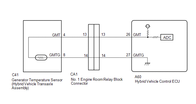
WIRING DIAGRAM
PROCEDURE
| 1. | CHECK CONNECTOR CONNECTION CONDITION (HYBRID VEHICLE CONTROL ECU CONNECTOR) |
Click here
| Result | Proceed to |
|---|---|
| OK | A |
| NG (The connector is not connected securely.) | B |
| NG (The terminals are not making secure contact or are deformed, or water or foreign matter exists in the connector.) | C |
| B | .gif) | CONNECT SECURELY |
| C | | REPAIR OR REPLACE HARNESS OR CONNECTOR |
|
.gif)
| 2. | CHECK CONNECTOR CONNECTION CONDITION (NO. 1 ENGINE ROOM RELAY BLOCK CA1 CONNECTOR) |
Click here
| Result | Proceed to |
|---|---|
| OK | A |
| NG (The connector is not connected securely.) | B |
| NG (The terminals are not making secure contact or are deformed, or water or foreign matter exists in the connector.) | C |
| B | | CONNECT SECURELY |
| C | | REPAIR OR REPLACE HARNESS OR CONNECTOR |
|
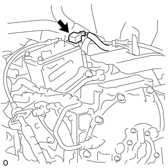
| 3. | CHECK CONNECTOR CONNECTION CONDITION (GENERATOR TEMPERATURE SENSOR CONNECTOR) |
| (a) Check the connection condition of the generator temperature sensor connector and the contact pressure of each terminal. Check the terminals for deformation, and check the connector for water ingress and foreign matter. Click here OK: - The connector is connected securely. - The terminals are not deformed and are connected securely. - No water or foreign matter in the connector. |
|
| Result | Proceed to |
|---|---|
| OK | A |
| NG (The connector is not connected securely.) | B |
| NG (The terminals are not making secure contact or are deformed, or water or foreign matter exists in the connector.) | C |
| B | | CONNECT SECURELY |
| C | | REPAIR OR REPLACE HARNESS OR CONNECTOR |
|
| 4. | READ VALUE USING TECHSTREAM (MOTOR TEMP NO2) |
(a) Connect the Techstream to the DLC3.
(b) Turn the power switch on (IG).
(c) Enter the following menus: Powertrain / Hybrid Control / Data List / Motor Temp No2.
Powertrain > Hybrid Control > Data List| Tester Display |
|---|
| Motor Temp No2 |
(d) Read the Data List.
(e) Turn the power switch off.
| 215°C (419°F) | | GO TO STEP 7 |
| Same as actual temperature | | REPAIR OR REPLACE HARNESS OR CONNECTOR |
|
| 5. | INSPECT HYBRID VEHICLE TRANSAXLE ASSEMBLY (GENERATOR TEMPERATURE SENSOR) |
| (a) Disconnect the C41 generator temperature sensor connector. |
|
| (b) Measure the resistance according to the value(s) in the table below. Standard Resistance:
|
|
(c) Reconnect the C41 generator temperature sensor connector.
| NG | | REPLACE HYBRID VEHICLE TRANSAXLE ASSEMBLY |
|
| 6. | CHECK HYBRID VEHICLE CONTROL ECU |
| (a) Connect terminals 26 (GMT) and 27 (GMTG) of the A60 hybrid vehicle control ECU connector. |
|
(b) Connect the Techstream to the DLC3.
(c) Turn the power switch on (IG).
(d) Enter the following menus: Powertrain / Hybrid Control / Data List / Motor Temp No2.
Powertrain > Hybrid Control > Data List| Tester Display |
|---|
| Motor Temp No2 |
(e) Read the Data List.
OK:
| Tester Display | Condition | Specified Condition |
|---|---|---|
| Motor Temp No2 | Terminals A60-26 (GMT) and A60-27 (GMTG) connected Power switch on (IG) | 215°C (419°F) |
(f) Turn the power switch off.
| OK | | REPAIR OR REPLACE HARNESS OR CONNECTOR |
| NG | | REPLACE HYBRID VEHICLE CONTROL ECU |
| 7. | INSPECT HYBRID VEHICLE TRANSAXLE ASSEMBLY (GENERATOR TEMPERATURE SENSOR) |
| (a) Disconnect the C41 generator temperature sensor connector. |
|
| (b) Measure the resistance according to the value(s) in the table below. Standard Resistance:
|
|
(c) Reconnect the C41 generator temperature sensor connector.
| NG | | REPLACE HYBRID VEHICLE TRANSAXLE ASSEMBLY |
|
| 8. | CHECK HARNESS AND CONNECTOR (GENERATOR TEMPERATURE SENSOR - HYBRID VEHICLE CONTROL ECU) |
(a) Disconnect the C41 generator temperature sensor connector.
(b) Disconnect the A60 hybrid vehicle control ECU connector.
(c) Measure the resistance according to the value(s) in the table below.
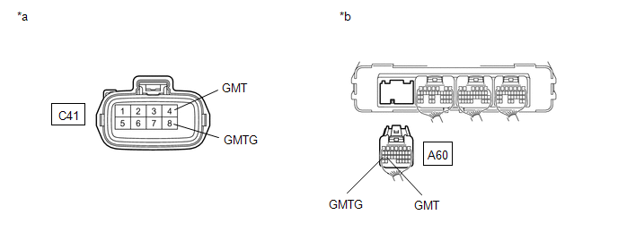
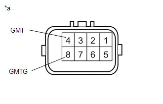
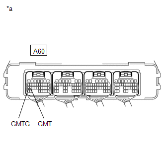
| *a | Front view of wire harness connector (to Generator Temperature Sensor) | *b | Rear view of wire harness connector (to Hybrid Vehicle Control ECU) |
Standard Resistance (Check for Open):
| Tester Connection | Condition | Specified Condition |
|---|---|---|
| C41-4 (GMT) - A60-26 (GMT) | Power switch off | Below 1 Ω |
| C41-8 (GMTG) - A60-27 (GMTG) | Power switch off | Below 1 Ω |
Standard Resistance (Check for Short):
| Tester Connection | Condition | Specified Condition |
|---|---|---|
| C41-4 (GMT) or A60-26 (GMT) - Body ground and other terminals | Power switch off | 10 kΩ or higher |
| C41-8 (GMTG) or A60-27 (GMTG) - Body ground and other terminals | Power switch off | 10 kΩ or higher |
(d) Reconnect the A60 hybrid vehicle control ECU connector.
(e) Reconnect the C41 generator temperature sensor connector.
| OK | | REPLACE HYBRID VEHICLE CONTROL ECU |
| NG | | REPAIR OR REPLACE HARNESS OR CONNECTOR |
READ NEXT:
 Drive Motor "A" Position Sensor Circuit (P0A3F-243,P0A40-500,P0A41-245)
DTC SUMMARY MALFUNCTION DESCRIPTION These DTCs indicate the resolver output signal is abnormal. The cause of this malfunction may be one of the following: Area Main Malfunction Description Step
Drive Motor "A" Position Sensor Circuit Range / Performance (P0A40-504)
DTC SUMMARY MALFUNCTION DESCRIPTION This DTC indicates that an overvoltage in the inverter has occurred. The cause of this malfunction may be one of the following: Area Main Malfunction Descripti
Drive Motor "A" Position Sensor Circuit Range / Performance (P0A40-506,P0A40-808)
DTC SUMMARY MALFUNCTION DESCRIPTION These DTCs indicate that a large current flowed in the inverter for the motor. The cause of this malfunction may be one of the following: Area Main Malfunction
SEE MORE:
Disassembly
DISASSEMBLY PROCEDURE 1. REMOVE MILLIMETER WAVE RADAR SENSOR ASSEMBLY Click here 2. REMOVE FRONT TELEVISION CAMERA ASSEMBLY (w/ Panoramic View Monitor System) Click here 3. REMOVE FRONT CENTER ULTRASONIC SENSOR (w/ Intuitive Parking Assist System) Click here 4. REMOVE FRONT BUMPER EXTENSION
Components
COMPONENTS ILLUSTRATION *1 DECK FLOOR BOX LH *2 NO. 3 DECK BOARD SUB-ASSEMBLY *3 REAR DECK FLOOR BOX *4 NEGATIVE AUXILIARY BATTERY TERMINAL N*m (kgf*cm, ft.*lbf): Specified torque - - ILLUSTRATION *1 FRONT DOOR ARMREST SET BRACKET LH *2 FRONT DOOR BELT MOU
