Lexus NX: Glass Humidity Sensor Circuit (B14AA)
DESCRIPTION
The air conditioning thermistor assembly (glass humidity sensor) detects cabin humidity. The voltage of the air conditioning thermistor assembly (glass humidity sensor) changes in accordance with cabin humidity. The air conditioning amplifier assembly reads the changes in output voltage of the air conditioning thermistor assembly (glass humidity sensor).
The glass humidity sensor is integrated with the air conditioning thermistor assembly.
| DTC No. | Detection Item | DTC Detection Condition | Trouble Area | Memory | Note |
|---|---|---|---|---|---|
| B14AA | Glass Humidity Sensor Circuit | Open or short in glass humidity sensor circuit |
| Memorized (4 seconds or more)* | - |
- *: The air conditioning amplifier assembly stores this DTC if the malfunction has occurred for the period of time indicated in the brackets.
WIRING DIAGRAM
.png)
CAUTION / NOTICE / HINT
HINT:
The air conditioning thermistor assembly must be replaced if the glass humidity sensor is malfunctioning.
PROCEDURE
| 1. | READ VALUE USING TECHSTREAM |
(a) Connect the Techstream to the DLC3.
(b) Turn the power switch on (IG).
(c) Turn the Techstream on.
(d) Enter the following menus: Body Electrical / Air Conditioner / Data List.
(e) Check the value(s) by referring to the table below.
Body Electrical > Air Conditioner > Data List| Tester Display | Measurement Item | Range | Normal Condition | Diagnostic Note |
|---|---|---|---|---|
| Glass Humidity | Glass humidity | Min.: 0.00% Max.: 100.00% | Actual glass humidity is displayed | - |
| Tester Display |
|---|
| Glass Humidity |
OK:
The display is as specified in the normal condition column.
| OK | .gif) | REPLACE AIR CONDITIONING AMPLIFIER ASSEMBLY |
|
.gif)
| 2. | CHECK AIR CONDITIONING AMPLIFIER ASSEMBLY |
| (a) Disconnect the air conditioning thermistor assembly (glass humidity sensor) connector. |
|
(b) Measure the voltage according to the value(s) in the table below.
Standard Voltage:
| Tester Connection | Switch Condition | Specified Condition |
|---|---|---|
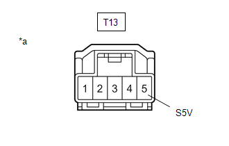
| T13-5 (S5V) - Body ground | Power switch off | Below 1 V |
| T13-5 (S5V) - Body ground | Power switch on (IG) | 4.75 to 5.25 V |
| NG | | GO TO STEP 4 |
|
| 3. | INSPECT AIR CONDITIONING THERMISTOR ASSEMBLY (GLASS HUMIDITY SENSOR) |
(a) Inspect the air conditioning thermistor assembly (glass humidity sensor) connector.
Click here .gif)
| NG | | REPLACE AIR CONDITIONING THERMISTOR ASSEMBLY (GLASS TEMPERATURE SENSOR) |
|
| 4. | CHECK HARNESS AND CONNECTOR (AIR CONDITIONING THERMISTOR ASSEMBLY [GLASS HUMIDITY SENSOR] - AIR CONDITIONING AMPLIFIER ASSEMBLY) |
(a) Disconnect the T13 air conditioning thermistor assembly (glass humidity sensor) connector.
(b) Disconnect the I50 air conditioning amplifier assembly connector.
(c) Measure the resistance according to the value(s) in the table below.
Standard Resistance:
| Tester Connection | Condition | Specified Condition |
|---|---|---|
| T13-3 (RH) - I50-28 (RH) | Always | Below 1 Ω |
| T13-1 (SEG3) - I50-35 (SG-5) | Always | Below 1 Ω |
| T13-5 (S5V) - I50-31 (S5-4) | Always | Below 1 Ω |
| T13-3 (RH) or I50-28 (RH) - Body ground | Always | 10 kΩ or higher |
| T13-1 (SEG3) or I50-35 (SG-5) - Body ground | Always | 10 kΩ or higher |
| T13-5 (S5V) or I50-31 (S5-4) - Body ground | Always | 10 kΩ or higher |
| OK | | REPLACE AIR CONDITIONING AMPLIFIER ASSEMBLY |
| NG | | REPAIR OR REPLACE HARNESS OR CONNECTOR |
READ NEXT:
 Lost Communication with Front Panel LIN (B14B2)
DESCRIPTION The air conditioning control assembly communicates with the air conditioning amplifier assembly through the LIN communication system. If the LIN communication system malfunctions, the air
Refrigerant Shortage (B14B8)
DESCRIPTION This DTC is stored if the amount of refrigerant in the air conditioning system is insufficient. The air conditioning amplifier assembly receives the ambient temperature signal, refrigerant
Hybrid Battery Voltage System Isolation Fault (P0AA6-611)
DESCRIPTION This DTC is stored if there is insulation malfunction in the high-voltage circuit in the air conditioning system. Possible causes are poor insulation in the compressor with motor assembly,
SEE MORE:
Removal
REMOVAL PROCEDURE 1. REMOVE AIR CONDITIONING UNIT ASSEMBLY Click here 2. REMOVE BLOWER ASSEMBLY (a) Disconnect the No. 1 blower damper servo sub-assembly connector. (b) Detach the 3 clamps and remove the air conditioning harness assembly. (c) Remove the 2 screws. (d
Voice is not Recognized
PROCEDURE 1. CHECK CONDITION (a) While paying attention to the condition of the spoken voice command, perform a voice recognition operation. OK: Voice command is recognized normally. HINT:
When the voice command is recognized, the content of the voice command is displayed in the voice r
