Lexus NX: Headlight Beam Level Control Motor LH Malfunction (B2417,B2418)
Lexus NX Service Manual / Vehicle Exterior / Lighting (ext) / Automatic Headlight Beam Level Control System (for Triple Beam Headlight) / Headlight Beam Level Control Motor LH Malfunction (B2417,B2418)
DESCRIPTION
| DTC No. | Detection Item | DTC Detection Condition | Trouble Area |
|---|---|---|---|
| B2417 | Headlight Beam Level Control Motor LH Malfunction |
| Headlight unit assembly LH |
| B2418 | Headlight Beam Level Control Motor RH Malfunction |
| Headlight unit assembly RH |
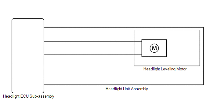
WIRING DIAGRAM
PROCEDURE
| 1. | CHECK FOR DTC |
(a) Clear the DTCs.
Click here .gif)
(b) Turn the power switch on (IG) and wait for at least 10 seconds or more.
(c) Check for DTCs.
Click here
OK:
DTC B2417 or B2418 is not output.
| Result | Proceed to |
|---|---|
| OK | A |
| NG (DTC B2417 is output) | B |
| NG (DTC B2418 is output) | C |
| A | .gif) | USE SIMULATION METHOD TO CHECK |
| B | | REPLACE HEADLIGHT UNIT ASSEMBLY LH |
| C | | REPLACE HEADLIGHT UNIT ASSEMBLY RH |
READ NEXT:
 Headlight Leveling Motor LH Communication Malfunction (B2424,B2410,B2411,B2425)
DESCRIPTION Each headlight ECU sub-assembly and headlight swivel and leveling motor communicate via LIN communication. The headlight swivel and leveling motor operates according to power supplied and
Initialization has not been Performed (B2450)
DESCRIPTION The vehicle height must be initialized for the headlight ECU sub-assembly LH to perform auto leveling control. DTC No. Detection Item DTC Detection Condition Trouble Area B245
Height Control Sensor Data Out of Range When Initializing (B2452)
DESCRIPTION The headlight ECU sub-assembly LH stores this DTC if the value from the rear height control sensor sub-assembly LH is out of range when performing initialization of the headlight ECU sub-a
SEE MORE:
Components
COMPONENTS ILLUSTRATION *1 DECK FLOOR BOX LH *2 NO. 3 DECK BOARD SUB-ASSEMBLY *3 REAR DECK FLOOR BOX *4 AUXILIARY BATTERY NEGATIVE TERMINAL N*m (kgf*cm, ft.*lbf): Specified torque - - ILLUSTRATION *A for Compact Size Spare Tire *B for Full Size Spare Tire
Adjustment (one Time Recognition)
ADJUSTMENT (ONE TIME RECOGNITION) CAUTION / NOTICE / HINT NOTICE: Make sure to read Before Starting Adjustment before proceeding with work. Click here PROCEDURE 1. SECURE APPROPRIATE AREA FOR PERFORMING LEARNING (a) Park the vehicle on a level surface. HINT:
Make sure that the target recogni
© 2016-2026 Copyright www.lexunx.com
