.gif)
- Power switch on (READY)
- air conditioning system not operated
Lexus NX: Heater Water Pump Circuit
Lexus NX Service Manual / Vehicle Interior / Heating / Air Conditioning / Air Conditioning System / Heater Water Pump Circuit
DESCRIPTION
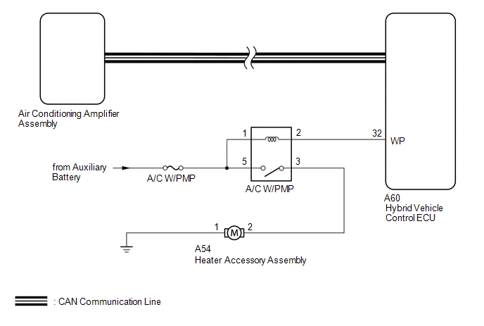
The heater accessory assembly sends engine coolant to the heater core assembly while the engine is stopped to prevent heater effectiveness from becoming low. Directed by the air conditioning amplifier assembly, the hybrid vehicle control ECU operates the A/C W/PMP relay and drives the heater accessory assembly.
WIRING DIAGRAM
CAUTION / NOTICE / HINT
NOTICE:
Inspect the fuses for circuits related to this system before performing the following inspection procedure.
PROCEDURE
| 1. | CHECK CAN COMMUNICATION SYSTEM |
(a) Using the Techstream, check if the CAN communication system is functioning normally.
Click here .gif)
OK:
CAN communication system DTCs are not output.
| NG | .gif) | GO TO CAN COMMUNICATION SYSTEM |
|
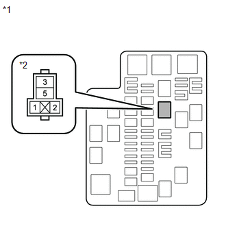
| 2. | INSPECT HYBRID WATER PUMP RELAY (A/C W/PMP) |
(a) Check the signal reading of the hybrid water pump relay (A/C W/PMP relay).
Click here
OK:
A normal signal reading is output.
| NG | | REPLACE HYBRID WATER PUMP RELAY |
|
| 3. | INSPECT HEATER ACCESSORY ASSEMBLY |
(a) Remove the heater accessory assembly.
Click here
(b) Inspect the heater accessory assembly.
Click here
| NG | | REPLACE HEATER ACCESSORY ASSEMBLY |
|
| 4. | CHECK HARNESS AND CONNECTOR (HYBRID WATER PUMP RELAY - BATTERY) |
| (a) Remove the hybrid water pump relay (A/C W/PMP relay). |
|
(b) Measure the voltage according to the value(s) in the table below.
Standard Voltage:
| Tester Connection | Switch Condition | Specified Condition |
|---|---|---|
| Relay terminal 1 - Body ground | Power switch off | 11 to 14 V |
| Relay terminal 5 - Body ground | Power switch off | 11 to 14 V |
| NG | | REPAIR OR REPLACE HARNESS OR CONNECTOR |
|
| 5. | CHECK HARNESS AND CONNECTOR (HEATER ACCESSORY ASSEMBLY - HYBRID WATER PUMP RELAY AND BODY GROUND) |
(a) Disconnect the A54 heater accessory assembly connector.
(b) Remove the hybrid water pump relay (A/C W/PMP relay).
(c) Measure the resistance according to the value(s) in the table below.
Standard Resistance:
| Tester Connection | Condition | Specified Condition |
|---|---|---|
| A54-2 - Relay terminal 3 | Always | Below 1 Ω |
| A54-2 or Relay terminal 3 - Body ground | Always | 10 kΩ or higher |
| A54-1 - Body ground | Always | Below 1 Ω |
| NG | | REPAIR OR REPLACE HARNESS OR CONNECTOR |
|
| 6. | CHECK HARNESS AND CONNECTOR (HYBRID WATER PUMP RELAY - HYBRID VEHICLE CONTROL ECU) |
(a) Remove the hybrid water pump relay (A/C W/PMP relay).
(b) Disconnect the A60 hybrid vehicle control ECU connector.
(c) Measure the resistance according to the value(s) in the table below.
Standard Resistance:
| Tester Connection | Condition | Specified Condition |
|---|---|---|
| Relay terminal 2 - A60-32 (WP) | Always | Below 1 Ω |
| Relay terminal 2 or A60-32 (WP)- Body ground | Always | 10 kΩ or higher |
| NG | | REPAIR OR REPLACE HARNESS OR CONNECTOR |
|
| 7. | CHECK HYBRID VEHICLE CONTROL ECU |
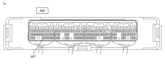
| *a | Component with harness connected (Hybrid Vehicle Control ECU) | - | - |
(a) Remove the hybrid vehicle control ECU with the connectors still connected.
Click here
(b) Measure the voltage according to the value(s) in the table below.
Standard Voltage:
| Tester Connection | Switch Condition | Specified Condition |
|---|---|---|
| A60-32 (WP) - Body ground | | 11 to 14 V |
| A60-32 (WP) - Body ground |
| Below 2 V |
| OK | | PROCEED TO NEXT SUSPECTED AREA SHOWN IN PROBLEM SYMPTOMS TABLE |
| NG | | REPLACE HYBRID VEHICLE CONTROL ECU |
READ NEXT:
 PTC Heater Circuit
DESCRIPTION The air conditioning amplifier assembly sends operation signals to the PTC heater relays when quick heater assembly operation conditions are met. Based on the signals from the air conditio
Ambient Temperature Display System
DESCRIPTION The thermistor assembly (ambient temperature sensor) is installed in front of the cooler condenser assembly to detect the ambient temperature which is used to control the air conditioning
ECO Switch Circuit
DESCRIPTION When the integration control and panel assembly (ECO mode switch) is turned on, the air conditioning amplifier assembly receives an integration control and panel assembly (ECO mode switch)
SEE MORE:
Removal
REMOVAL PROCEDURE 1. REMOVE CONSOLE ARMREST ASSEMBLY Click here 2. REMOVE UPPER REAR CONSOLE PANEL Click here 3. REMOVE UPPER NO. 2 CONSOLE PANEL GARNISH Click here 4. REMOVE UPPER NO. 1 CONSOLE PANEL GARNISH Click here 5. REMOVE INSTRUMENT SIDE PANEL LH Click here 6. REMOVE NO. 1
Disassembly
DISASSEMBLY PROCEDURE 1. REMOVE MILLIMETER WAVE RADAR SENSOR ASSEMBLY Click here 2. REMOVE FRONT TELEVISION CAMERA ASSEMBLY (w/ Panoramic View Monitor System) Click here 3. REMOVE FRONT CENTER ULTRASONIC SENSOR (w/ Intuitive Parking Assist System) Click here 4. REMOVE FRONT BUMPER EXTENSION MO
© 2016-2026 Copyright www.lexunx.com
