Lexus NX: ECO Switch Circuit
DESCRIPTION
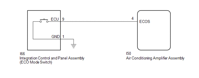
When the integration control and panel assembly (ECO mode switch) is turned on, the air conditioning amplifier assembly receives an integration control and panel assembly (ECO mode switch) ON signal and controls the air conditioning to enhance fuel efficiency.
WIRING DIAGRAM
CAUTION / NOTICE / HINT
NOTICE:
When the auxiliary battery is disconnected or the air conditioning amplifier assembly is replaced, be sure to perform servo motor initialization.
Click here .gif)
PROCEDURE
| 1. | READ VALUE USING TECHSTREAM |
(a) Connect the Techstream to the DLC3.
(b) Turn the power switch on (IG).
(c) Turn the Techstream on.
(d) Enter the following menus: Body Electrical / Air Conditioner / Data List.
(e) Check the values by referring to the table below.
Body Electrical > Air Conditioner > Data List| Tester Display | Measurement Item | Range | Normal Condition | Diagnostic Note |
|---|---|---|---|---|
| ECO Switch | Integration control and panel assembly (ECO mode switch) | ON or OFF | ON: Integration control and panel assembly (ECO mode switch) being turned and held at ECO position OFF: Integration control and panel assembly (ECO mode switch) not turned | - |
| Tester Display |
|---|
| ECO Switch |
OK:
Integration control and panel assembly (ECO mode switch) condition displayed on the Techstream changes with the actual switch operation.
| OK | .gif) | PROCEED TO NEXT SUSPECTED AREA SHOWN IN PROBLEM SYMPTOMS TABLE |
|
.gif)
| 2. | INSPECT INTEGRATION CONTROL AND PANEL ASSEMBLY (ECO MODE SWITCH) |
(a) Remove the integration control and panel assembly (ECO mode switch).
Click here
(b) Inspect the integration control and panel assembly (ECO mode switch).
Click here
| NG | | REPLACE INTEGRATION CONTROL AND PANEL ASSEMBLY (ECO MODE SWITCH) |
|
| 3. | CHECK HARNESS AND CONNECTOR (INTEGRATION CONTROL AND PANEL ASSEMBLY [ECO MODE SWITCH] - AIR CONDITIONING AMPLIFIER ASSEMBLY AND BODY GROUND) |
(a) Disconnect the I66 integration control and panel assembly (ECO mode switch) connector.
(b) Disconnect the I50 air conditioning amplifier assembly connector.
(c) Measure the resistance according to the value(s) in the table below.
Standard Resistance:
| Tester Connection | Condition | Specified Condition |
|---|---|---|
| I50-4 (ECOS) - I66-9 (ECU) | Always | Below 1 Ω |
| I50-4 (ECOS) or I66-9 (ECU) - Body ground | Always | 10 kΩ or higher |
| I66-1 (GND) - Body ground | Always | Below 1 Ω |
| OK | | REPLACE AIR CONDITIONING AMPLIFIER ASSEMBLY |
| NG | | REPAIR OR REPLACE HARNESS OR CONNECTOR |
READ NEXT:
 IG Power Source Circuit
DESCRIPTION The main power source is supplied to the air conditioning amplifier assembly when the power switch is on (IG). The power is used for operating the air conditioning amplifier assembly, serv
Back-up Power Source Circuit
DESCRIPTION The back-up power source circuit for the air conditioning amplifier assembly is shown below. Power is supplied even when the power switch is off. The power is used for diagnostic trouble c
SEE MORE:
How To Proceed With Troubleshooting
CAUTION / NOTICE / HINT HINT: *: Use the Techstream. PROCEDURE 1. VEHICLE BROUGHT TO WORKSHOP
NEXT 2. CUSTOMER PROBLEM ANALYSIS
NEXT 3. CONNECT TECHSTREAM TO DLC3* HINT: If the display indicates a communication malfunction, inspect the DLC
Shift Paddle Switch Circuit
DESCRIPTION When the shift lever is in S, the shift range position can be changed freely using the shift paddle switch of the transmission shift switch assembly. WIRING DIAGRAM PROCEDURE 1. READ VALUE USING TECHSTREAM (SPORT UP SHIFT SENS STATE, SPORT DWN SHIFT SENS STATE) (a) Connect the
